Siemens SSD-series Desigo Fire Safety Modular System Status Displays, Data Sheet

File Preview
Click below to download for free
Click below to download for free
File Data
| Name | siemens-ssd-series-desigo-fire-safety-modular-system-status-displays-data-sheet-8790465132.pdf |
|---|---|
| Type | |
| Size | 1.00 MB |
| Downloads |
Text Preview
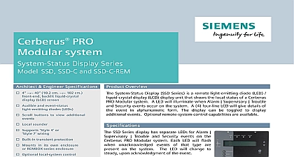
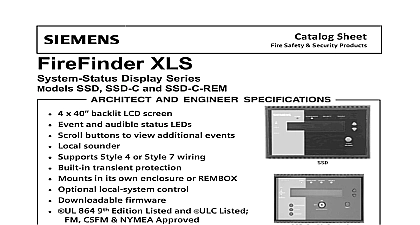
Fire Safety system Display Series SSD SSD C and SSD C REM Architect Engineer Specifications Product Overview 4 40 10.2 cm 102 cm backlit liquid crystal LCD screen Audible and event status diodes LEDs Scroll buttons to view additional Local sounder Supports 4 or 7 wiring Built in transient protection Mounts in its own enclosure or enclosure Optional local system control Downloadable firmware UL864 CAN ULC S576 Listed CSFM NYCFD Approved Technologies Division System Status Display SSD Series is a remote light emitting diode LED display LCD display unit that shows the local status of a Desigo Safety Modular system A LED will illuminate when Alarm Supervisory and Security events occur on the system A 4 four line LCD will give of the event in alphanumeric form The display can be toggled to display events Optional remote system control capabilities are available Specifications SSD Series display has separate LEDs for Alarm Trouble and Security events on the Fire Safety Modular system Each LED will when unacknowledged events of that type are on the system The LED will change to upon acknowledgment of the event there are two 2 LEDs that indicate the state of circuits on the system one 1 LED to that the circuits are active and one 1 LED to the circuits have been silenced LCD display on the Model SSD series display has 4 rows 40 characters for each row When the Fire Safety Modular system is in its normal state with no events present the display annunciate the system ID information the date the time of day an event occurs on the system the LCD display will the event type and address the time of the event custom message for that address the usage of the and whether the event is acknowledged or not the display will show the total of all types of events present on the The display has a backlight feature that upon receiving any event information when any operator buttons are pressed SSD C REM Series SSD C Series Sheet 7326 continued local sounder is included with the Model SSD series display that operates when any events are displayed on the The sounder can be optionally disabled through software programming Pressing any operator buttons will the local sounder when an event is present SSD Series display has two 2 display control buttons that are used to display the next or the previous event in the sequence and a local sounder silence button Programming for the SSD Series display is done with Zeus D programming tool SSD C and Model SSD C REM have three 3 additional control buttons for acknowledging events silencing circuits and resetting the system Model SSD C has an integral key switch that enables these control buttons to Model SSD C REM is located within a locked cabinet so no additional key switch is required for enabling the buttons SSD Series display is remotely connected to the H Net communication bus from any Model NIC C interface in a Fire Safety Modular system enclosure using Class B Style 4 or Class A Style 7 wiring 24VDC is required to run SSD Series display and can be provided from a Model PSC 12 Power Supply or PSX 12 Power Supply Extender in the Fire Safety Modular system enclosure Power from other UL Listed 24VDC power sources is also acceptable SSD Series display has screw terminals capable of supporting 12 to 22 gage wires The H Net communication from the Fire Safety Modular system can be terminated on the SSD Series display or may pass through for communication with modules Diagnostic LEDs on the SSD Series display indicate power and communication status SSD and SSD C can be mounted in a 2 two gang electrical box or a 4 four inch square electrical box No flush kit is required The unit is approximately 10 1 2 26.7cm wide 6 1 8 15.2cm high and1 1 2 3.8cm deep Model SSD C REM is mounted in a Model REMBOX2 or Model REMBOX4 Remote Lobby Enclosure or any CAB inner door Model SSD C REM requires two 2 module spaces in the remote lobby enclosure and its bracket the mounting of four 4 inner door modules such as Model SCM 8 or Model LCM 8 modules below the The inner door module spaces are arranged in two 2 rows of 2 two module spaces Temperature and Humidity Range Products are UL 864 9th Edition Listed for indoor dry locations within a temperature range of 120 3 49 2 32 3 0 2 and a relative humidity of 93 2 at a temperature of 90 3 32 2 Technologies Division for Ordering TYPE Display Display with control 500 634773 Display control for remote lobby enclosure 500 633772 Remote Lobby Enclosure 500 633914 Remote Lobby Enclosure Control Module Plate Ratings VOLTAGE max at 24 VDC VDC Nominal 31 VDC max filtered auxiliary regulated power limited power may be used to provide power to Model The power supply must be UL Listed for Fire Signaling Application Be sure to also Model SSD C in the battery calculations SSD INTL max at 24 VDC VOLTAGE VDC Nominal 31 VDC max filtered auxiliary regulated power limited power may be used to provide power to Model The power supply must be UL Listed for Fire Signaling Application max at 24 VDC VOLTAGE VDC Nominal 31 VDC max filtered auxiliary regulated power limited power supply may used to provide power to Model SSD C REM The supply must be UL ULC approved for Fire Signaling Application Be sure to also include SSD C REM battery Technologies Division NOTICE The information contained in this data sheet document is intended only a summary and is subject to change without notice product s described here has have a specific instruction sheet s cover various technical limitation and liability information of install type instruction sheets as well as the General Product and Limitations document which also contains important data provided with the product and are available from the Manufacturer contained in the aforesaid type of documentation should be consulted a fire safety professional before specifying or using the product further questions or assistance concerning problems that might arise relative to the functioning of the equipment please contact Manufacturer Fire Safety Industry Inc Technologies Division Fernwood Road Florham Park NJ 07932 973 593 2600 2017 New Issue 0


