Siemens SZE-4X Zone Output Expander Module, Installation Instructions

File Preview
Click below to download for free
Click below to download for free
File Data
| Name | siemens-sze-4x-zone-output-expander-module-installation-instructions-8542730169.pdf |
|---|---|
| Type | |
| Size | 707.17 KB |
| Downloads |
Text Preview
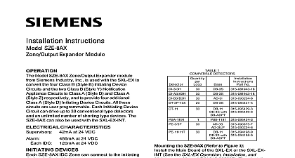
Installation Instructions SZE 4X Expander Module Model SZE 4X Zone Output Expander module Siemens Industry Inc is used with the SXL EX provide an additional four Class B Style B Initiating Circuits four Form C Relays and four Open Output Circuits All the devices on these are user programmable Each inititiating circuit can drive up to 30 conventional type and an unlimited number of shorting type The SZE 4X can also be used with the CHARACTERISTICS at 24 VDC IDC Relay at 24 VDC at 24 VDC at 24 VDC DEVICES SZE 4X IDC Zone can connect to the initiating indicated below Up to 30 smoke detectors may be used on an zone Compatible detectors are listed in 1 Detectors of different models are not to mixed or matched on a system The PBA 1191 Beam Detector may be used as in Figure 4 Only one PBA 1191 Beam may be used on an SZE 4X zone and total on the system Any number of shorting type devices can be used a SZE 4X zone to Figures 2 3 and 4 for the wiring of the shorting type devices and the beam devices all system power before first battery and then AC power up connect the AC first then the battery Industry Inc Technologies Division Park NJ 315 096018 8 the SZE 4X Refer to Figure 1 the Main Board of the SXL EX or SXL EX INT the SXL EX Operation Installation and Mainte Manual P N 315 095997 Then install the in the lower portion of the EN SX enclosure following the steps listed below Screw the four standoffs onto the four studs in the lower portion of the SXL EX Place the SZE 4X over the four standoffs Using four screws provided fasten the SZE 4X to the standoffs Figure 2 for wiring connections from the SZE 4X the SXL EX Main Board to the SXL EX Operation Installation and Manual P N 315 095997 for program instructions related to IDC Zones and Open and Relay Outputs Building Technologies Ltd Safety Security Products Kenview Boulevard Ontario 5E4 Canada 1 Mounting the SZE 4X Module Open Collector Electrical Rating Table Open Collector Electrical Rating Table Note 6 Note 6 and Negative Ground Fault and Negative Ground Fault at 100K for Terminals on TB 3 at 100K for Terminals on TB 3 External 24VDC External 24VDC Listed Regulated Listed Regulated Filtered power Filtered power Note 6 Note 6 1 Programmable 1 Programmable 2 Programmable 2 Programmable 3 Programmable 3 Programmable 4 Programmable 4 Programmable SXL EX SXL EX Board Board TB 3 TB 3 External External Supply Supply not available not available to to Main Main TB 3 TB 3 Note 5 Note 5 Programmable Programmable Programmable C C 1 1 6 6 C C 4 4 6 6 C C 3 3 6 6 C C 2 2 6 6 JP3 JP3 SXL EX SXL EX 5 5 6 6 7 7 8 8 Listed EOL Device Listed EOL Device 1 2W P N 140 820386 1 2W P N 140 820386 Supervised Supervised B Style B B Style B COMPATIBLE DETECTOR CHART and COMPATIBLE DETECTOR CHART and DEVICE CIRCUIT ELECTRICAL RATINGS DEVICE CIRCUIT ELECTRICAL RATINGS The SXL EX Control Panel meets NFPA 72 requirements C ELECTRICAL RATINGS DEVICE CIRCUIT Ratings All field wiring must be in accordance with at 30 VDC range 18.2 26.8 VDC filtered 70 Article 760 at 120 VAC Resistive Only current 6mA Do not make any wiring connections the System is powered Form C relay contacts are shown de They are not suitable for motor pilot duty Combined current output for NAC1 NAC2 auxiliary outputs is limited to 3.0 amps Equipment connected to these terminals be located within the same room all cases the Siemens Industry Inc Number is the compatibility including the Control Panel and all Compatible Initiating COLLECTOR RATING TABLE max at 26.4 VDC max Only 2 Wiring Diagram current 120mA max Maximum line impedance of 25 ohms IDC zone All IDC zones are supervised and power per NFPA 70 Article 760 Each IDC zone must use at least 18 300V insulation color coded wire low voltage circuits where local require conduit Where local permit use limited energy cable rated at 300V Each IDC zone supports one initiating in alarm Maximum line capacitance is 10uF per C D E NOT NOT IDC IDC RESISTOR RESISTOR 1 4W P N 140 820188 1 4W P N 140 820188 Device Wiring Diagram 4 Device Wiring Diagram Detector and Shorting Type Device 3 Diagram 315 096018 8