Siemens SZE-8AX Zone Output Expander Module, Installation Instructions

File Preview
Click below to download for free
Click below to download for free
File Data
| Name | siemens-sze-8ax-zone-output-expander-module-installation-instructions-8967102435.pdf |
|---|---|
| Type | |
| Size | 718.48 KB |
| Downloads |
Text Preview
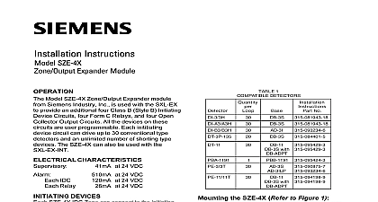
Installation Instructions SZE 8AX Expander Module Model SZE 8AX Zone Output Expander module Siemens Industry Inc is used with the SXL EX to the four Class B Style B Initiating Device and the two Class B Style Y Notification Circuits to Class A Style D and Class A Z respectively and to provide four additional A Style D Initiating Device Circuits All these are user programmable Each Inititiating Device can drive up to 30 conventional type detectors an unlimited number of shorting type devices The can also be used with the SXL EX INT CHARACTERISTICS at 24 VDC IDC at 24 VDC at 24 VDC DEVICES SZE 8AX IDC Zone can connect to the initiating indicated below Up to 30 smoke detectors may be used on an zone Compatible detectors are listed in 1 Detectors of different models are not to mixed or matched on a system The PBA 1191 Beam Detector may be used as in Figure 4 Only one PBA 1191 Beam may be used on an SZE 8AX zone eight total on the system Any number of shorting type devices can be used an SZE 8AX zone to Figures 2 3 and 4 for the wiring of the the shorting type devices and the beam devices all system power before first battery and then AC power up connect the AC first then the battery the SZE 8AX Refer to Figure 1 the Main Board of the SXL EX or the SXL EX See the SXL EX Operation Installation and Manual P N 315 095997 Then install SZE 8AX in the lower portion of the EN SX by following the steps listed below Screw the four standoffs onto the four studs in the lower portion of the SXL EX Place the SZE 8AX over the four standoffs Using four screws provided fasten the SZE 8AX to the standoffs Figure 2 for wiring connections from the to the SXL EX Main Board to the SXL EX Operation Installation and Manual P N 315 095997 Program 9 for programming instructions to enable the related to IDC Zones and Notification Circuits The SZE 8AX must be enabled to Industry Inc Technologies Division Park NJ 315 096022 8 Building Technologies Ltd Safety Security Products Kenview Boulevard Ontario 5E4 Canada 1 the SZE 8AX IDC IDC C D E NOT NOT RESISTOR RESISTOR 1 4W P N 140 820188 1 4W P N 140 820188 Device Wiring Diagram 4 Wiring Diagram Detector and Shorting Type Device Wiring 3 8 WIRES PIN 8 OF and Negative Ground Fault at 100K for terminals TB2 TB10 at 10K for terminals TB1 and TB11 4 1 2 3 4 5 6 7 8 3 TB7 OF A Z A D DEVICE CIRCUIT Ratings range 18.2 26.8 VDC filtered current 6mA current 120mA max Maximum line impedance of 25 ohms IDC zone All IDC zones are supervised and limited per NFPA 70 Article 760 Each IDC zone must use at least 18 300V insulation color coded wire low voltage circuits where local require conduit Where local permit use limited energy cable rated at 300V Each IDC zone supports one initiating Maximum line capacitance is 10uF per in alarm 315 096022 8 The SXL EX Control Panel meets 72 Local requirements All field wiring must be in accordance NFPA 70 Article 760 Do not make any wiring connections the System is powered all cases the Siemens Industry model number is the compat identifier including the Control modules s and all compat initiating devices Refer to P N 315 096363 for list of notification appliances maximum number allowed per 2 Wiring Diagram APPLIANCE CIRCUIT Ratings Application 16V 32VDC filtered current 1.5mA max current 1.5A max Each NAC rated at 1.5A 16 32 VDC Maximum loop resistance is 1.5 at 1.5A 2.0 ohms at 1.0A 3.0 at 0.75A All NACs must use at least 14 AWG insulation color coded wire for low circuits where local codes require Where local codes permit use energy cable rated at 300V All NACs are power limited per NFPA Article 760 For synchronized notification use of either a DSC or PAD 3 is required