Siemens TSM-1X Intelligent Test Switch Module with Dual Isolators, Installation Instructions

File Preview
Click below to download for free
Click below to download for free
File Data
| Name | siemens-tsm-1x-intelligent-test-switch-module-with-dual-isolators-installation-instructions-0372684951.pdf |
|---|---|
| Type | |
| Size | 734.67 KB |
| Downloads |
Text Preview
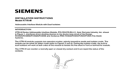
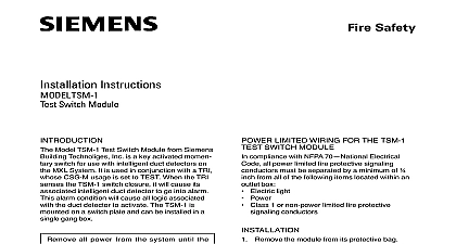
Instructions TSM 1X Test Switch Module with Dual Isolators Model TSM 1X Intelligent Test Switch Module P N from Siemens Industry Inc is an key activated momentary switch T 45 a tri color LED indicator for use with intelligent detectors or other compatible intelligent devices on Device Loop Circuit of Desigo and Cerberus PRO Fire Alarm Systems to Figure 1 The key activation will cause its intelligent duct detectors or other smoke and compatible devices to go into alarm alarm condition will cause all logic associated the duct detector to activate The 3 color LED of module will show the status of its associated duct detector The TSM 1X is mounted on a plate and can be installed in a 3 inch deep gang box TSM 1X module supports two operation modes insensitive mode and isolator mode The can be wired for either mode refer to Figures to 4 During the isolator mode the built in dual will work at both sides of the module to the line short in front or behind the module precautions for handling Sensitive Devices Refer to Figure 2 to locate the programming on back of the TSM 1X To connect the TSM 1X to the DPU insert the plug from the DPU provided with the Programmer Tester into programming holes To prevent potential damage to the DPU DO connect a TSM 1X to the DPU until all of the same polarity are removed from device line of the TSM 1X Follow the steps in the DPU Manual P N 315 to program the TSM 1X to the desired Record the device address on the label on the side of the TSM 1X module Add a logic function in the system configuration Document ID A6V10315023 with the duct detector or other compatible devices that will be tested The TSM 1X now be installed and wired to the system Figure 1 TSM 1X Intelligent Test Switch Module holes polarity insensitive can be inserted any direction 2 to the DPU Plug Industry Inc Technologies Division Park New Jersey INSTRUCTIONS Deactivate P2 circuit by either or of the following Using the PMI bypass the being modified and or physically the circuit from the P2 source to the wiring diagrams in Figures 3 and 4 and the TSM 1X to the device line of Desigo and Cerberus FC922 FC924 FV922 FV924 Fire Alarm Document ID A6V10315023 The recommended wire size is as follows AWG minimum AWG maximum LIMITED WIRING FOR THE TSM 1X SWITCH MODULE compliance with NFPA 70 Electrical all power limited fire protective signaling must be separated by a minimum of from all of the following items located within an box Electric light Power Class 1 or non power limited fire protective conductors Remove the module from its protective bag the TSM 1X in a user supplied UL standard single gang box minimum 3 inches deep is Refer to Figure 5 Terminate all field wires to the TSM 1X as for your application Refer to the diagrams shown in Figures 3 and 4 Insert the face plate and attach the cover plate the two screws provided Refer to Figure 5 the device line up to 30 of any devices in polarity insensitive with 20 ohms max line resistance be isolated between two modules in mode in a Class A Style 6 wiring the device line up to 30 of any devices in polarity insensitive with 20 ohms max line resistance be isolated behind one module in mode in a Class B Style 4 wiring HLIM isolator module and SBGA 34 base cannot be used in the same with the modules in isolator mode the system until system normal is displayed on panel Activate the momentary switch by turning key to the right the TSM 1X key switch is activated the message is received by the panel The then sends a reduced alarm threshold to the duct detectors or other compatible devices This causes the detector to alarm the LED of the TSM 1X will change colors the system The panel will restore the alarm threshold and the system back to next device control panel previous device 3 Isolator Mode Wiring next device control panel previous device 1 Line 2 1 2 4 Polarity Insensitive Mode Wiring 5 Mounting View TSM 1X Test Switch Module does not perform all of the required smoke detector tests as in NFPA Standard 72 Please refer to the instructions that accompany the smoke for the complete test requirements RATINGS AND INDICATORS voltage average current RMS 32 Vdc LED of TSM 1X will mimic the LED of the associated duct detectors or other compatible devices The logic function is setup in the system configuration tool LED flashing rate is shown in the chart below Color Intervals Flashes supervisory operation is in trouble power or need to be replaced security disclaimer products and solutions provide security functions to ensure the secure operation of building comfort fire security management and physical security systems The security functions on these products and solutions important components of a comprehensive security concept is however necessary to implement and maintain a comprehensive state of the art security concept that is to individual security needs Such a security concept may result in additional site specific preventive to ensure that the building comfort fire safety security management or physical security system for your site operated in a secure manner These measures may include but are not limited to separating networks protecting system components user awareness programs defense in depth etc additional information on building technology security and our offerings contact your Siemens sales or project We strongly recommend customers to follow our security advisories which provide information on the security threats patches and other mitigation measures http www siemens com cert en cert security advisories htm Statement and usage of equipment not in accordance with instructions manual may result in of radio frequency energy to radio communications and use equipment in accordance with instructions manual the following information equipment generates uses and can radiate radio frequency energy and if not installed and used in accordance with the manual may cause interference to radio communications has been tested and found to comply with the limits for a Class A computing device pursuant to Part 15 of FCC Rules which designed to provide reasonable protection against such interference when operated in a commercial environment of this equipment in a residential area is likely to cause interference in which case the user at his own expense will be to take whatever measures may be required to correct the interference Industry Inc Technologies Division Park New Jersey Document ID A6V101055486 en a P N A5Q00062968 Canada Ltd North Service Road East Ontario 0H6 Canada