Siemens TSP-40A Logging Printer, Installation Instructions

File Preview
Click below to download for free
Click below to download for free
File Data
| Name | siemens-tsp-40a-logging-printer-installation-instructions-9015462783.pdf |
|---|---|
| Type | |
| Size | 692.48 KB |
| Downloads |
Text Preview
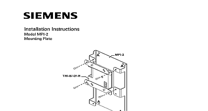
Installation Instructions TSP 40A Printer System Model TSP 40A Logging Printer from Siemens Industry Inc is used in MXL and CAB2 or CAB3 enclosures and provides a paper record of the activity of system You may install one printer for each MKB 2 Keyboard Annunciator on your system or one printer for each Operator Interface OI on your FireFinder Fire Safety Modular Cerberus PRO Modular System additional information on the MXL MXLV System refer to the MXL MXLV Manual 315 092036 For additional information on the FireFinder XLS Desigo Fire Safety PRO Modular System refer to the FireFinder XLS Control Panel Operation and Maintenance Manual P N 315 033744 the Desigo Fire Modular Manual Document ID A6V11231620 or the Cerberus PRO Modular Document ID A6V11231627 Instructions for installing the TSP 40A in a System are found in P N 315 049949 TSP 40A is mounted on four studs in the lower right hand corner of the MBR MP plate using the 4 standoffs and 4 nuts provided with the TSP 40A install the TSP 40A in an MME 3 or MLE 6 enclosure place the standoffs over the studs in the lower right hand corner of the MBR MP mounting plate as shown in 1 Mount the TSP 40A on the 4 standoffs and secure in place with the four provided For mounting the MBR MP in an MME 3 or MLE 6 enclosure refer to 315 094882 Printer 4 4 4 1 the TSP 40 on the MBR MP Mounting Plate 315 034933 3 Inc Inc Inc Industry Inc Inc TTTTTececececechnologies Di Di Di Division Di System Desigo Fire Safetey Modular Cerberus PRO Modular mounting the TSP 40A printer in a FireFinder XLS Desigo Fire Safety Modular PRO Modular System refer to installation instructions P N 315 049950 Installation TSP 40A comes with two cables two conductor power cable and a data cable cables are used for installation only in an MXL MXLV System System data cable P N 600 290607 connects to P2 on the TSP 40A and to P4 on the or PSR 1 two conductor power cable P N 600 290606 has a plug on one end that to P1 on the TSP 40A The connection of the plug on the other end of the is dependent on whether or not an MOM 4 is installed in the panel no MOM 4 is installed connect the two conductor power cable to P3 on MMB or to P1 on the PSR 1 a MOM 4 is installed connect the two coductor power cable to P8 on the to Figure 2 for the location of the cable connections on the TSP 40A to an MXL System P4 ON OR PSR 1 P3 ON MMB OR P1 ON PSR 1 NO MOM 4 P8 ON MOM 4 IF MOM 4 2 the TSP 40A to an MXL MXLV System System Desigo Fire Safetey Modular Cerberus PRO Modular cables for the FireFinder XLS Desigo Fire Safety Modular Cerberus PRO Modular are included in the TSP XC cable kit 500 849950 Refer to the TSP XC instructions P N 315 049950 for wiring information Ratings 5VDC Module Current 24VDC Module Current 24VDC Module Current Industry Inc Technologies Division 315 034933 3 the Paper Roll install the paper roll on the TSP 40A follow the steps listed below See Figures 3 4 5 the two knobs on the printer guide plate and drop the paper guide exposing the printer mechanism the paper dispensing roller the roller through the paper roll and place the paper in the dispenser the loose end of the paper against the printer to Figure 4 Push the Up Lever to the down position to the tension on the roller Feed the loose end of the paper behind the at the top of the printer mechanism the paper by turning the large gear on the right side of the printer clockwise Advance the paper until one inch extends out from printer mechanism Hold the paper with both hands and gently pull until 12 inches of paper out from the printer mechanism Return the Up Lever to upright position Note the Up Lever must be in the upright for the printer to print the paper through the slot in the guide plate 7 8 Return the guide plate to its normal position and secure it with the two 9 Remove the take up reel by pulling straight out on both sides of the reel Separate the reel by pulling on both ends revealing the paper retention clip Figure 3 Figure 5 Place the loose end of the paper over the larger part of the reel and slide smaller end of the reel over the paper This locks the paper onto the reel Make sure that the drive gear on the reel is on the left side Then put the reel back into the retaining clips Press down until the reel snaps into Be sure that the drive gear engaged the drive motor gear Take up any slack in the paper by turning the takeup reel until the paper taut Industry Inc Technologies Division 315 034933 3 the Paper Roll the paper roll following the instructions above when the paper supply is low that you do not lose a printed record of messages sent to a full printer buffer paper roll is TSP 40 PP P N 500 691888 CLEAR to resume printing after changing the paper roll or wait about 5 minutes the printer to resume printing automatically 3 the Paper Industry Inc Technologies Division 315 034933 3 UP LEVER POSITION PAPER ROLLER 4 Mechanism Detail 5 the Takeup Reel Industry Inc Technologies Division 315 034933 3 security disclaimer products and solutions provide security functions to ensure the secure operation of building comfort safety security management and physical security systems The security functions on these products and are important components of a comprehensive security concept is however necessary to implement and maintain a comprehensive state of the art security concept that is to individual security needs Such a security concept may result in additional site specific action to ensure that the building comfort fire safety security management or physical security for your site are operated in a secure manner These measures may include but are not limited to networks physically protecting system components user awareness programs defense in depth additional information on building technology security and our offerings contact your Siemens sales or department We strongly recommend customers to follow our security advisories which provide on the latest security threats patches and other mitigation measures http www siemens com cert en cert security advisories htm Industry Inc Technologies Division 315 034933 3 PAGE HAS BEEN LEFT INTENTIONALLY BLANK Industry Inc Technologies Division 315 034933 3 Industry Inc Technologies Division Park NJ Canada Ltd North Service Road East Ontario 0H6 Canada ID A6V10239137 315 034933 3