Siemens TSRM-312 Remote Relay, Installation and Operation Manual

File Preview
Click below to download for free
Click below to download for free
File Data
| Name | siemens-tsrm-312-remote-relay-installation-and-operation-manual-8362940571.pdf |
|---|---|
| Type | |
| Size | 1.16 MB |
| Downloads |
Text Preview
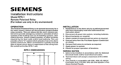
TSRM 312 Relay Kenview Blvd Ont L6T 5E4 Industry Inc Fernwood Florham Park 07932 U S A Rev 2 2013 Installation and Operation Manual 1 Installation 1 Setup 2 2 Switches 3 of the Relays 4 5 Features 6 Warranty Warning Information 7 Please Read Carefully 7 Warranty 9 Procedure 9 of Warranties 9 of Warranty Repairs 10 Installation and Operation Manual Installation TSRM 312 Smart Relay Module provides twelve supervised configurable relays and comes complete with a black mount the TSRM 312 open the front door and mount the backbox to the wall using the four screws provided This may also be mounted to a 4 square electrical box There are two conduit areas provided at the bottom of enclosure KNOCKOUT Setup Setup 120 ohm EOL JW51 is used on last between and ONLY Remove all the RS 485 on last jumpers except for the TSRM 312 only address Switch for address is for factory only 2 3 5 6 7 8 ON IN OUT NO NC NO NC NO NC NO NC NO NC NO NC 7 8 9 10 11 12 FAIL 1 2 3 4 5 6 NO NC NO NC NO NC NO NC NO NC NO NC jumpers for STATUS LEDS jumpers JW48 and JW50 intact board 24 Volts from filtered Auxiliary at the Fire Alarm Panel if enabled via DIP switch DSW1 4 this LED illuminates steadily amber when auxiliary disconnect is activated the Fire Alarm Panel transmit receive LED flashes green as long as there is communication with the Fire Alarm Panel ON illuminates steadily green as long as there is power to the relay board FAIL will illuminate steadily amber when CPU fails at the Fire Alarm Panel Function USE ONLY JUMPER INSTALLED USE ONLY JUMPER INSTALLED USE ONLY JUMPER INSTALLED Installation and Operation Manual Switches DIP Switch DSW 1 4 DSW1 6 DSW1 7 and DSW 1 8 inclusive are always to be set to OFF is one bank of DIP switches to be set DSW1 is found at the top left hand corner and is used to select the smart address Valid addresses are 1 to 6 inclusive for TXR 320 Series Fire Alarm Panels Set address as follows Switch DSW1 1 to 1 3 Switch DSW1 5 TXR 320 only to enable added support for hazard zone message for the TXR 320 This option is enabled by putting DSW1 to the position When this option is enabled relay 1 to 6 will show the status for Hazard Area 1 and Hazard 2 as shown in the table below Area 1 Area 2 Release Release Switch DSW1 4 set to OFF Switch DSW1 6 set to OFF Switch DSW1 7 set to OFF Switch DSW1 8 set to OFF of the Relays of the Relays twelve Relays may be configured to operate alone or in combination with other relays on the board This is accomplished by jumper selection on the Smart Relay module The following illustration explains how relays are configured SELECTION Relay turns on when common is active Relay turns on when common is active Jumper is NOT installed on center pin only GREEN 1 CONNECTION terminal provides normally closed contacts terminal provides normally open contacts jumper is installed on normally open NO if the jumper is not installed on any selection the relay is not connected to the terminals 6 JUMPER turns on relay when the zone is active does not turn on the relay when 1 is active Jumper is installed OR WITH ADJACENT ZONE installed this relay 1 works in with relay 2 removed relay 1 does not with the adjacent relay 2 example if jumper is installed 1 2 and 2 3 then all the three relays be on if any one of relays 1,2 or 3 is No jumper installed connected one pin only Installation and Operation Manual from the last TSRM 312 to the next TSRM 312 and so on then from the first TSRM 312 to the Fire Alarm There are only two connections to be made one for power and one for the RS 485 loop Ensure that the 120 E O L resistor is connected to the RS 485 positive and negative terminals on last TSRM 312 RS 485 Wiring to the TSRM 312 is recommended to be Twisted Shielded Pair The wire gauge may be 22 AWG up to 2000 ft 20 AWG up to 4000 ft 24V DC field wiring needs to be of an appropriate gauge for the number of smart relays and the total wiring run See Current Drain for Battery Calculations page 6 and calculate the Maximum current for all smart relays together All circuits are power limited and must use type FPL FPLR or FPLP Power Limited Cable Accidentally connecting any of the 24V DC wires to the RS 485 wiring will result in damage to Annunciator and or to the Fire Alarm Control Panel to which it is connected Maximum for all Relays Wiring Run to Last Smart Relay Loop Features Features may be mounted on a 4 square Electrical Box or on a wall Specifications VDC nominal voltage LEDs DISCNN Aux Disconnect TX RX Transmit Receive PWR ON CPU FAIL and individual status LED indicators DC 1A maximum per contact resistive load programmable relays available Expandable 30 mA Max Alarm 140 mA Max All LEDs illuminated 140 mA Max Drain for Battery Calculations maximum normal current drain will be during Lamp Test