Siemens VCC2001-A1 Voice CPU Card, Installation Instructions
File Preview
Click below to download for free
Click below to download for free
File Data
| Name | siemens-vcc2001-a1-voice-cpu-card-installation-instructions-4780516923.pdf |
|---|---|
| Type | |
| Size | 857.69 KB |
| Downloads |
Text Preview
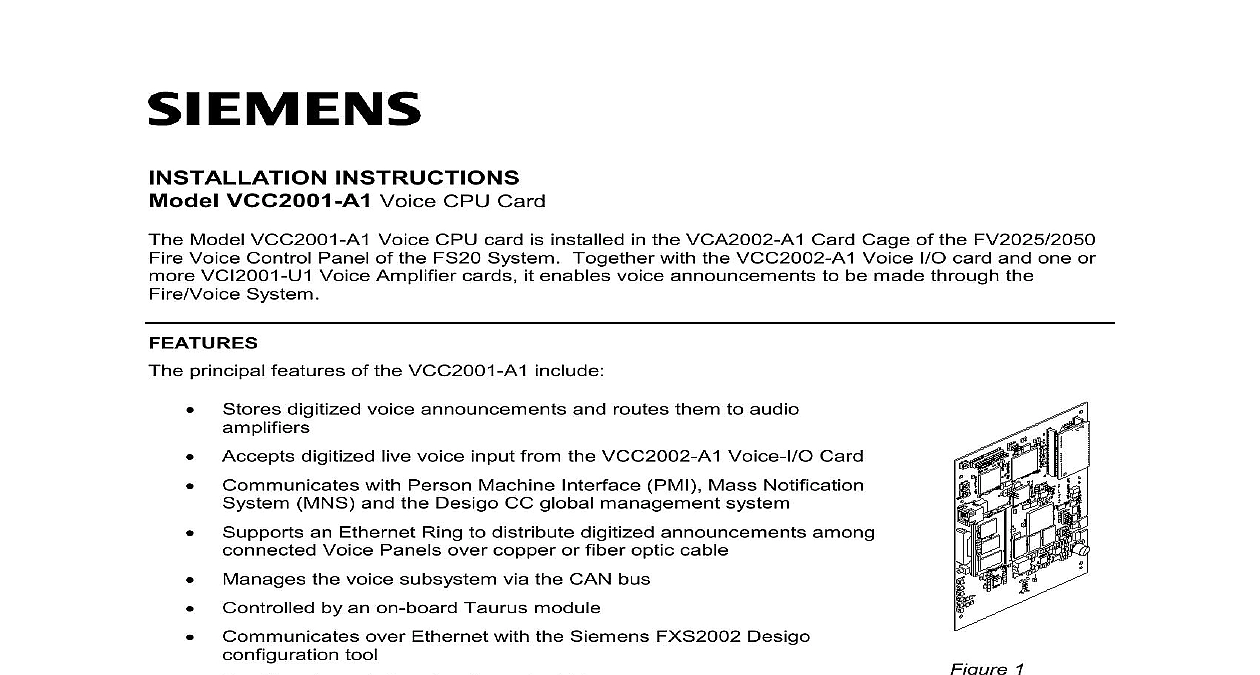
INSTRUCTIONS VCC2001 A1 Voice CPU Card Model VCC2001 A1 Voice CPU card is installed in the VCA2002 A1 Card Cage of the FV2025 2050 Voice Control Panel of the FS20 System Together with the VCC2002 A1 Voice I O card and one or VCI2001 U1 Voice Amplifier cards it enables voice announcements to be made through the System principal features of the VCC2001 A1 include Stores digitized voice announcements and routes them to audio Accepts digitized live voice input from the VCC2002 A1 Voice I O Card Communicates with Person Machine Interface PMI Mass Notification MNS and the Desigo CC global management system Supports an Ethernet Ring to distribute digitized announcements among Voice Panels over copper or fiber optic cable Manages the voice subsystem via the CAN bus Controlled by an on board Taurus module Communicates over Ethernet with the Siemens FXS2002 Desigo tool Provides degrade functionality to the Voice system Delivers 3.3VDC power to the VCC2002 A1 Voice I O module Provides connectors for Barix Voice over IP VoIP plug in module Provides connector for Ethernet plug in modules ROHS compliant and meets performance specifications within the commercial temperature operational status via LEDs 1 CPU Card Can be used in the UL and ULC markets are no pre installation operations needed for the VCC2002 A1 Voice CPU Card refer to Figure 2 The VCC2001 A1 Voice CPU Card stores and routes digitized voice Those announcements can be sent to the local loudspeakers and also to remote Panels which then broadcast the announcements to speaker groups in their vicinity The Voice Card manages both pre recorded announcements which are stored digitally in an on board Audio and live emergency announcements that originate using microphones These live analog are digitized by the associated VCC2002 A1 Voice I O Card and are then routed to both Voice CPU Card and to speakers which are co located with the remote microphones or recorded announcements can be originated remotely at a networked FV2025 2050 Fire Control Panel at an MNS or at a VR2005 U1 Remote Microphone station They are to the host Panel for local broadcast After being received and digitized by the Voice I O Card such announcements are routed by the VTO2001 A1 Voice CPU Card the appropriate VCI2001 U1 Voice Amplifier Card s for conversion back to analog and broadcast over the local loudspeaker system PANEL TOOL OR MNS OVER ETHERNET OR COPPER OR COPPER CODEC DIGITAL ANNOUNCEMENT AUDIO CONTROL CARD 2 Voice CPU Card Signal Flow and Indicators VCC2001 A1 contains a card RESET button and six LEDs located the card edge and visible through the Card Cage cover see Figure 3 meaning of each LED is described in Table 1 When the CPU card is only the green power LED should be steady on If that LED starts the panel has switched over to battery power When an alarm the red alarm LED should also turn on Any of the yellow LEDs on indicates a fault condition either with the card itself or with the going to it The only exception to this is the card fail LED It will for a time after the card is reset while it is initializing itself and during a load CPU Comms Fail Fault Comms Fail Fail NORMAL Fail Yellow Fault Comms Fail 3 Voice CPU Card LEDs active in the Voice of Ethernet fault detection in the mode of Voice communication the system during start up and SW Steady on is a card failure card voltages are at the value Steady ON when powered the system power Blinking when running on power 1 Panel LEDs electrical power prior to working on equipment Open the middle and lower inner doors of the FV2025 2050 Fire Voice Control Panel Unscrew the latch on the center bottom of the VCA2002 A1 Card Cage front cover and slide cover up until it clears the cage assembly HANDLE BACKPLANE 4 Voice CPU Card Showing Pushbuttons and USP Connectors Orienting the VCC2001 A1 Voice CPU Card as shown in Figure 4 gently insert the card into backplane connector marked X202 Use the raised channel guides on the inside top and of the Card Cage to guide it into place inserting the VCC2001 A1 Voice CPU Card into the backplane connector grippng the top and bottom of the Card Cage Instead push gently on the of the molded plastic card handle until the card snaps into place Be sure the card is perpendicular to the front of the card cage and is positioned the two indented metal cards guides in the top and bottom of the Card The card needs to be between all three sets of card guides as it is slid into to correctly mate with the backplane connector avoid damaging the VCC2001 A1 card or the backplane connector DO NOT THE CARD INTO POSITION the Fire Voice Panel is to be connected to an Ethernet Ring install the required VN2002 A1 or VN2003 A1 Ethernet Modules though the knockouts at the top the Card Cage as directed in the installation instructions enclosed with these modules Replace the Card Cage cover by re inserting it into the top of the Card Cage and sliding it until it reaches bottom Screw the latch back into the Card Cage cover the VCC2001 A1 Voice CPU Card from the Card Cage First remove power from the card cage present remove any Ethernet modules connected to the VCC2001 A1 Voice CPU Card Unscrew the latch on the center bottom of the Card Cage front cover and slide the cover up Grip the VCC2001 A1 card by the molded plastic card handle and pull the card gently out of backplane connector Replace the Card Cage cover and reinsert the latch for the VCC2001 A1 Voice CPU Card P N A5Q00057954B are made through card s edge connector when the VCC2001 A1 is installed into the VCA2002 A1 Card one or two Ethernet modules that plug into the VCC2001 A1 through the top panel of the Card Cage instructions for the VCC2001 A1 are provided in the following Siemens Industry Inc Technologies Division documents A6V10380472 Installation Instructions for the Model VCA2002 A1 Card Cage A6V10370415 Installation Instructions for the Model VN2001 A1 Ethernet Module 10 100 Tx A6V10370419 Installation Instructions for the Model VN2002 A1 MM and VN2003 A1 Ethernet Modules multi mode and single mode optical fiber RATINGS following table gives the voltage and current requirements for the VCC2001 A1 Voice CPU The amount of current used by the card is dependent upon whether or not the card is in the state Voice CPU Card VDC normal operating voltage can between 19 and 28 volts 200mA Alarm conditions exist in the Voice system Alarm or Evacuation event has occurred All outputs of the system are either or On security disclaimer products and solutions provide security functions to ensure the secure operation of building fire safety security management and physical security systems The security functions on these and solutions are important components of a comprehensive security concept is however necessary to implement and maintain a comprehensive state of the art security concept is customized to individual security needs Such a security concept may result in additional site preventive action to ensure that t