Siemens VN2002-A1 VN2003-A1 Ethernet Module (MM) (SM), Installation Instructions

File Preview
Click below to download for free
Click below to download for free
File Data
| Name | siemens-vn2002-a1-vn2003-a1-ethernet-module-mm-sm-installation-instructions-0374918265.pdf |
|---|---|
| Type | |
| Size | 958.65 KB |
| Downloads |
Text Preview
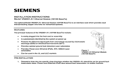
INSTRUCTIONS VN2002 A1 Ethernet Module MM VN2003 A1 Ethernet Module SM optional VN2002 A1 Ethernet Module MM multi mode and VN2003 A1 Ethernet Module SM are optical fiber interface cards which provide dual interconnecting optical links for systems principal features of both the VN2002 A1 and the VN2003 A1 include Easily plugged into the host card or assembly Automatically identified by the system at power up Can be used in the UL and ULC markets 1 Ethernet Module MM Ethernet Module SM are no pre installation steps associated with installation of either the VN2002 A1 Ethernet Module or VN2003 A1 Ethernet Module SM VN2002 A1 Ethernet Module MM and VN2003 A1 Ethernet Module SM can be used both in networks of FV2025 2050 Fire Voice Control Panels and in generic Ethernet systems in a Voice Network of FV2025 2050 Fire Voice Control Panels VN2002 A1 Ethernet Module MM and the VN2003 A1 Ethernet Module SM are optional circuit that plug into the VCC2001 A1 Voice CPU card to provide two cable connections which are used for links in an Ethernet Backbone network see Figure 3 Each link in a Backbone network is of any other link It can be implemented as either copper wire or fiber optic cable without any to what is used for the other links in the network Each end of a link must use the same type of card That is if a VN2002 A1 Ethernet Module MM is used at one end of a link another VN2002 Ethernet Module MM has to be installed at the other end of the link for the link to operate correctly same constraint applies to using the VN2003 A1 Ethernet Module SM For installation instructions applicable to copper based links see Siemens Industry Inc Building Division document number A6V10370415 Installation Instructions for the Model Ethernet Module 10 100 BaseTx Backbone is a dual fiber self healing redundant ring network that is able to detect failures and then isolate and recover from them using an alternate routing FIBER ETHERNET BACKBONE 10 100 BASE Tx VN2002 A1 MM SM ETHERNET FIBER LINKS THE SAME MM OR SM MUST BE AT BOTH ENDS OF LINK CARD CARD CARD 3 Network Topology in a Voice Network of FV2025 2050 Panels in a Generic Ethernet Network addition to their use in Ethernet backbone networks of FV2025 2050 Fire Voice Control Panels as in Figure 3 the VN2002 A1 Ethernet Module MM and the VN2003 A1 Ethernet Module SM be used to support fiber connections among standalone FN2012 A1 Ethernet Switches modular two LEDs on the VN2002 3 A1 which are located next to the fiber connectors indicate the following and Indicators Link established Signal activity the VN2002 3 A1 Ethernet Module MM or SM in a Voice Network of FV2025 2050 Fire Control Panels Power down the FV2025 2050 Fire Voice Control Panel before mounting the Open the middle door of the FV2025 2050 Panel Unscrew the latch on the front of the Card Cage and remove the Card Cage cover a VCC2001 A1 Voice CPU is installed in card slot X202 remove it If no VCC2001 A1 is proceed to the next step Referring to Figure 4 if either or both of the knockouts for Ethernet modules are still present the Card Cage top panel remove them To avoid damage to sensitive electronic remove any burrs that may be present in the knockout opening the VCC2001 A1 Voice CPU card into card slot X202 according to instructions in Siemens Industry Inc Building Technologies Division document number Installation Instructions for the Voice CPU Card Refer to the site specific shop drawings to determine which type of fiber multi mode or is to be installed on the link to be implemented and which position on the CPU Card is to use that link For a link to be implemented using multimode fiber install a VN2002 A1 Ethernet For a link to be created using single mode fiber install a VN2003 A1 Ethernet Module MM CAGE TOP PANEL CAGE COVER GUIDE LATCH FOR MODULES GUIDE 4 Card Cage the first VN2002 3 A1 Ethernet Module through the specified knockout opening on top the VCA2002 A1 Card Cage and press it into the multi pin connector mounted on the Voice CPU card The multi pin connector is located approximately 21 2 below knockout opening as illustrated in Figure 5 Install the second module for the other link the same manner through the remaining knockout opening Tighten the fastening pin on the top of each module see Figure 6 by turning it clockwise the modules are firmly held in place by the Card Cage it becomes necessary to deinstall the VCC2001 A1 Voice CPU Module first remove the modules that have been mounted on it Replace the Card Cage cover by re inserting it into the top of the Card Cage and sliding it until it reaches bottom Screw the cover latch back into the Card Cage cover MODULE MM or SM A1 MODULE COPPER CONNECTOR 5 Modules installed in VCA2002 A1 Card Cage the VN2002 3 A1 Ethernet Module MM or SM in an FN2012 A1 Ethernet Switch Remove the screws fastening the cover to the body of the FN2012 A1 Ethernet Switch and lift the cover off the assembly Please refer to Figure 6 If necessary remove the knockouts in the side panel of the Ethernet Switch modular PIN FOR MODULES ETHERNET MODULAR ETHERNET MM OR SM FOR FASTENING PIN 6 the VN2002 3 A1 Ethernet Module in the FN2012 A1 Ethernet Switch Refer to the site specific shop drawings to determine which type of fiber multi mode or mode is to be installed on the link to be implemented and in which position of the box it is to be installed in For a link to be implemented using multi mode fiber up to 5 km 3 mi long install a Ethernet Module MM For a link to be created using single mode fiber up 40 km long 25 mi long install a Ethernet Module SM the VN2002 3 A1 Ethernet Module MM or SM through the knockout opening and press it into the multi pin connector mounted on the circuit card inside the switch The multi pin connector is located approximately 21 2 inches inside the opening Screw the fastening pin on the VN2001 A1 module into the mating hole in the side of the Ethernet Switch modular Replace the cover on the FN2012 A1 Ethernet Switch modular are no wiring operations associated with installing the VN2002 3 A1 onto the VCC2001 A1 CPU card or into an FN2012 A1 Ethernet Switch modular the site specific shop drawings for instructions on connecting FV2025 2050 Panels together to Ethernet rings using the VN2002 A1 Ethernet Module MM or the VN2003 A1 Ethernet SM Two fiber optic cables which are of the same mode type as the installed modules are to connect one module to the other in order to establish working a link fiber optic cables shall use LC connector type RATINGS following table lists the power requirements for the two types of fiber Ethernet modules There are variations of the power requirements for each type of module Those variations are caused by the module is installed either in the Voice CPU Card or the Ethernet Switch with either Aux or Bus power for the switch and VN2003 A1 Ethernet Modules Power Requirements Type Mult Mode Usage in the VCC2001 A1 Voice CPU Card mA in the FN2012 A1 Ethernet Switch power from Aux 20 30VDC 57mA in the FN2012 A1 Ethernet Switch power from the MoNET Bus 50mA in the FN2012 A1 Ethernet Switch power from Aux 20 30VDC 49mA in the FN2012 A1 Ethernet Switch power from the MoNET Bus 40mA Single Mode in the VCC2001 A1 Voice CPU Card mA SIGNAL ATTENUATION a signal travels down an optical fiber its level is reduced due to absorption by the fiber This sets the