Siemens VPM-MP Mounting Plate for the VPM, Installation Instructions

File Preview
Click below to download for free
Click below to download for free
File Data
| Name | siemens-vpm-mp-mounting-plate-for-the-vpm-installation-instructions-5619028374.pdf |
|---|---|
| Type | |
| Size | 1008.67 KB |
| Downloads |
Text Preview
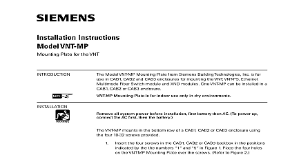
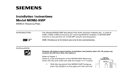
Installation Instructions VPM MP Plate for the VPM VPM MP mounting plate shown in Figure 1 used to mount one VPM module up to two cards and up to 2 HLI High Level Interface in a CC 5 footprint of a CAB enclosure This will support VESDA LaserFocus LaserPlus and Laser Scanner One VPM can support a total of 200 detectors VPM MP Mounting Plate is for indoor use only dry environments 1 Mounting Plate all system power before installation first battery then AC To power up the AC first then the battery installation kit consists of the following items VPM MP can be mounted in any location in a CAB enclosure CAB1 CAB1 X CAB2 CAB3 where a CC 5 card cage can be mounted Refer to Figure 2 for the mounting of the VPM socket card s and HLI card s on the VPM MP mounting plate 3 shows the VPM MP with one set of modules mounted on it A6V10347525 a en US Inc Inc Inc Industry Inc Inc TTTTTececececechnologies Di Di Di Division Di VPM MP mounting plate Four 4 keyholes for mounting VPM MP in CAB enclosure Studs for mounting VPM Standoffs for mounting socket card s for mounting HLI card s 4 s HLI high level interface card Socket card VPM VESDA peripheral module VPM MP mounting plate 2 Locations on VPM MP 3 Mounted on VPM MP the VPM the VPM to the VPM MP on the upper right side of the bracket Refer to 4 the VPM on the three studs provided for it on the VPM MP the three 8 32 kep lock hex nuts provided with the VPM MP over the and secure the VPM in place on the mounting plate the upper right hand mounting hole open This hole will be used the VPM MP is installed into the CAB enclosure peripheral module VPM VPM MP mounting plate 3 8 32 kep lock hex nuts Open mounting hole 4 the VPM on the VPM MP HLI Card s the HLI High Level Interface card s on the lower portion of the VPM MP Up two HLI cards can be mounted on a VPM MP Refer to Figure 5 Industry Inc Technologies Division A6V10347525 a en US the HLI card on the four studs on the lower portion on the VPM MP to Figure 2 for the location of the studs the four 3 8 male to female standoffs in the studs to secure the HLI in place on the VPM MP mounting plate see Figure 5 Securely the standoffs only one HLI card will be used place one 8 32 kep lock hex nut on top of of the four standoffs to retain them for possible future use two HLI cards will be used place the second card on top of the four Secure the second HLI card in place using one 8 32 kep lock nut on top of each of the four standoffs HLI high level interface card 1 3 8 male to female standoffs 8 32 kep lock hex nuts HLI high level interface card 2 mounting plate VESDA peripheral module 5 the HLI Card s on the VPM MP Socket Card s the Socket Card s on the left hand side of the VPM MP to the left of the VPM above the HLI card s Up to two Socket Cards can be mounted on the VPM MP to Figure 6 Mount Socket Card 1 on the four standoffs above the location where the is mounted Secure the socket card in place with four 8 32 x 5 16 screws provided a second Socket Card is used mount it on the four standoffs above card 1 and secure it in place with the remaining four 8 32 x 5 16 screws provided card 1 Socket card 2 8 32 x 5 16 sems square screws mounting plate mounting Socket card to VPM MP 6 Socket Card s on the VPM MP Industry Inc Technologies Division A6V10347525 a en US the VPM MP VPM MP mounts in any location in a CAB enclosure CAB1 CAB1 X CAB2 or where a CC 5 card cage can be mounted The VPM MP can also be mounted a CAB MP mounting plate Refer to Figure 7 mount the VPM MP in a CAB enclosure or on a CAB MP place three of four 10 32 x 3 8 pan Phillips screws supplied with the VPM MP in the in the enclosure backbox or CAB MP that line up with the bottom two top left keyhole openings in the VPM MP Tighten the screws halfway the VPM MP mounting plate over the three screws and drop it in the fourth 10 32 x 3 8 pan Phillips screw into the upper right hand hole This screw will pass through the VPM mounting hole and the stud in the CAB or CAB MP the screws to secure the VPM MP in place Typical CAB enclosure VPM MP mounting plate Keyholes for mounting VPM MP using x 3 8 pan Phillips screws 7 the VPM MP in a Typical CAB Enclosure to the VPM Installation Instructions P N A6V10347523 for wiring information VPM MP can be used in CAB1 CAB1 X CAB2 and CAB3 enclosures and on the Mounting Plate 9.50 x 14.25 Industry Inc Technologies Division Park NJ Canada Limited Technologies Division Kenview Boulevard Ontario L6T 5E4 Canada A5Q00051761 A6V10347525 a en US