Siemens VTO2004-U2 VTO2004-U3 Option Module (Microphone), Installation Instructions

File Preview
Click below to download for free
Click below to download for free
File Data
| Name | siemens-vto2004-u2-vto2004-u3-option-module-microphone-installation-instructions-5780269431.pdf |
|---|---|
| Type | |
| Size | 1.21 MB |
| Downloads |
Text Preview
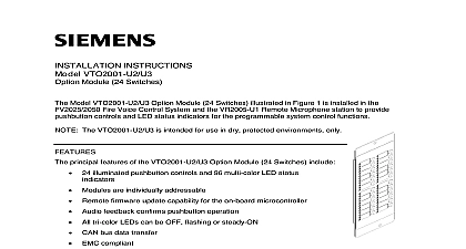
INSTRUCTIONS VTO2004 U2 U3 Module Microphone VTO2004 U2 U3 Option Module Microphone illustrated in Figure 1 is installed in the Fire System to enable firefighters and other safety personnel to make announcements and broadcast safety during emergencies and drills The VTO2001 U2 U3 can be installed in either or both the Fire Voice Control Panel or the VR2005 U1 Remote Microphone station The VTO2001 U2 U3 is intended for use in dry protected environments only principal features of the VTO2004 U2 U3 Option Module Microphone include microcontroller with remote firmware update capability Push to talk voice operation with centralized contention resolution Tune down relay muting of local speakers to prevent audio feedback squeal Automatic microphone gain control Microphone supervision of short and open circuit conditions Continuous status monitoring with automatic fault reporting EMC compliant ROHS compliant and meets performance specifications within the range Can be used in UL and ULC markets 1 Option Microphone two digit CAN Bus address for the VTO2004 U2 U3 Option Module Microphone is determined by the rotary DIP switches located on the back of the module as illustrated in Figure 2 The left switch sets tens digit of the address while the right switch sets the ones digit of the address The CAN bus is selected by the installer and may be set either before or after mounting the module To set the Bus address use a small flat bladed screwdriver to rotate the center of each switch until the arrow to the digit of the address which that switch represents relevant to assigning CAN bus addresses is provided in the following Siemens Industry Inc Technologies Division documents A6V10315013 FS20 Fire Detection and Voice Announcement System Planning Manual A6V10315023 FS20 Fire Detection and Voice Announcement System Configuration Manual 1 SWITCH TENS SWITCH ONES INTERFACE BOARD 2 view of the VTO2004 U2 U3 Option Module Microphone to Figure 3 The VTO2004 U2 U3 Option Module Microphone includes a hand held microphone a push to talk button and a flexible cable packaged together in a rectangular metal housing with a Microphone Interface Board MIB pictured in Figure 2 To use the microphone the depresses and holds the push to talk button until the control system enables the announcement be transmitted The operator continues to hold the button for the duration of the announcement To audio feedback during announcements the VTO2004 U2 U3 incorporates a tune down to mute the nearest loudspeaker s while the push to talk button is depressed and the microphone is and Indicators Active LED and the to Page LED are located on the front panel of the Option Module Microphone The Active LED illuminates when the presses the button on the microphone to request an audio connection to the Fire Voice Control Panel When the audio connection is made the LED extinguishes and the to Page LED is illuminated At that point the operator can talk the microphone The LED remains illuminated until the operator releases the push to talk button or is by a higher priority audio message HOUSING LED LED BUTTON MICROPHONE CABLE 3 view of the VTO2004 U2 U3 Option Module Microphone the VTO2004 in the FV2025 2050 Fire Voice Control Panel avoid mechanical interference with the VCA2002 A1 Card Cage the VTO2004 U2 U3 module must be mounted at the farthest right position of the middle window of the inner door as illustrated in 4 OUTPUT CONNECTORS X622 AND X623 WINDOW OF INNER DOOR MOUNTING STUD OPTION MICROPHONE MOUNTING STUD ACCESS HOLE 4 the VTO2004 in the FV22025 2050 Procdures NUT Refer to Figure 4 Mount the VTO2004 U2 U3 module by sliding its top and bottom mounting over the upper and lower mounting studs in the outside mounting position of the inner door Remove the mircrophone from the VTO2004 U2 U3 Place a 10 32 nut into a 3 8 inch nut driver and insert the nut driver through the mounting access in the rear of the VTO2004 U2 U3 Module Fasten that nut to the lower mounting stud Fasten a second 10 32 nut to the upper mounting stud to secure the VTO2004 U2 U3 module position Return the microphone to the VTO2004 U2 U3 Module the VTO2004 U2 U3 Option Module Microphone in the VR2005 U1 Remote Microphone 5 illustrates the mounting position for the VTO2004 U2 U3 Option Module Microphone on the door of the VR2005 U1 Remote Microphone station DOOR REMOTE MICROPHONE STATION MOUNTING STUD MOUNTING U2 U3 MODULE Procdures VOICE BOARD ACCESS HOLE NUT 5 the VTO2004 U2 U3 in the VR2005 U1 Remote Microphone Station procedure for mouting the VTO2004 U2 U3 in the VR2005 U1 Remote Microphone station is identical the procedure for mounting the VTO2004 U2 U3 in the FV2025 2050 Fire Voice Control Panel above the VTO2004 U2 U3 Option Module Microphone both in the FV2025 2050 Fire Voice Control and in the VR2005 U1 Remote Microphone station consists of two parts Wiring the VTO2004 U2 U3 Option Module Microphone to the nearest VTO2001 U2 U3 Module 24 Switches using the supplied ribbon cable Wiring the tune down relay on the VTO2004 U2 U3 Option Module Microphone to the audio and the muted speaker s I Wiring the VTO2004 U2 U3 Option Module Microphone wiring used to connect the VTO2004 U2 U3 Option Module Microphone varies according to whether module is mounted in a FV2025 2050 Panel or in a VR2004 U1 Remote Microphone station Wiring the VTO2004 U2 U3 Option Module Microphone when it is mounted in the Fire Voice Control Panel Please refer to Figure 6 Install an A5Q00055918D end of line EoL terminator on connector on top of the VTO2004 U2 U3 module a 16 conductor ribbon cable between connector X204 on top of the VTO2004 U2 U3 and connector X204 on the nearest VTO2001 Option Module 24 Switches Instructions for interconnecting the VTO2001 Option Module 24 Switches to each other and to VCA2002 A1 Card Cage are provided in Siemens Industry Inc Building Technologies document number A6V10370342 Installation Instructions for the VTO2001 U2 U3 Option 24 Switches END OF TERMINATION RIBBON JUMPER OPTION 24 SWITCHES INTERFACE OPTION MICROPHONE 6 the VTO2004 U2 U3 Option Module Microphone to the Nearest VTO2001 U2 U3 Option 24 Switches Wiring the VTO2004 U2 U3 Option Module Microphone when it is mounted in the VR2005 U1 Microphone station a 16 conductor ribbon cable between connector X204 on top of the VTO2004 U2 U3 and connector X204 on the nearest VTO2001 Option Module 24 Switches this is an intermediate microphone station in a system with several remote microphone stations a 16 conductor ribbon cable between connector X205 on top of the VTO2004 U2 U3 and connector X9 of the VTA2001 A1 Voice Terminal Board Otherwise if this is either a with only one remote microphone station or this is the end remote microphone station in a with several remote microphone stations install an A5Q00055918D end of line EoL on connector X205 on top of the VTO2004 U2 U3 module Instructions for connecting a VTO2004 U2 U3 module and the VTA2001 A1 Voice Terminal Board provided in Siemens Industry Inc Building Technologies Division document number Installation Instructions for the VTA2001 A1 Voice Terminal Board Class B II Wiring the Tune Down Relay tune down relay is a component of the Micropho