Siemens XDLC Class X Device Loop Card, Installation Instructions

File Preview
Click below to download for free
Click below to download for free
File Data
| Name | siemens-xdlc-class-x-device-loop-card-installation-instructions-6152798403.pdf |
|---|---|
| Type | |
| Size | 856.21 KB |
| Downloads |
Text Preview
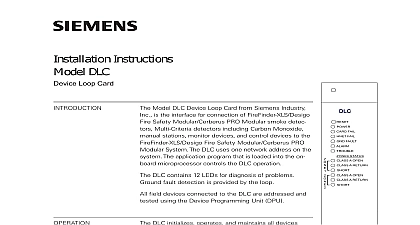
Installation Instructions XDLC X DCLC Device Loop Card Model XDLC Device Loop Card from Siemens Industry is the interface for connection of Desigo Fire Safety PRO Modular smoke detectors Multi detectors including Carbon Monoxide manual monitor devices and control devices to the Desigo Safety Modular Cerberus PRO Modular System The uses one network address on the system The program that is loaded into the on board micro controls the XDLC operation XDLC contains 16 LEDs for diagnosis of problems fault detection is provided by the loop field devices connected to the XDLC are addressed and using the Device Programming Unit DPU XDLC initializes operates and maintains all devices on the loop The XDLC communicates all relevant and event information such as alarms and troubles the PMI 2 PMI 3 OI C OI D PMI The sensitivity of any smoke detector can be checked and adjusted the PMI through the XDLC All information about the on the loop can be displayed on the PMI The XDLC the System polarity insensitive devices to be without generating errors PMI PMI 2 PMI 3 FCM2041 XDLC supports four Class A DCLA or Class X DCLC eight Class B DCLB parallel lines stubs of up to Desigo Fire Safety Modular Cerberus PRO Modular field devices as well as device accessories relay audible bases and remote lamps in any combina The microprocessor controls the on board isolators to any zone from the loop if one of them is shorted one zone is isolated from the loop the other zones still work FAIL FAIL FAULT 1 2 3 4 on board microprocessor provides the XDLC with the to function and initiate alarm conditions even if the PMI CPU fails The XDLC accomplishes this mode of operation by the communications with the PMI In the case of the failure of the PMI 1 Device Loop Card Inc Inc Inc Industry Inc Inc Infrastruct Infrastruct Infrastructureureureureure Infrastruct Infrastruct XDLC continues to monitor its associated devices and if any alarm device the XDLC will activate the outputs selected for mode of operation it will also signal other modules within its backplane as to the degrade alarm Note that output activation in degrade may take up to 60 seconds and that controlling releasing agents are not activated by operation mode operation is not the same as Mode as in ULC and Indicators front panel of the XDLC contains one reset switch 16 LEDs and three HNET switches as shown in Figure 1 A reset switch is located on the top of the panel Pushing the reset switch re initializes the XDLC operation LEDs follow the reset switch and their functions are defined as follows FAIL FAULT LEDS 1 8 ON When illuminated indi the power for the XDLC is applied the card Blinks during firmware or if download has failed OFF When illuminated indi the card microprocessor has failed OFF When illuminated indi that the HNET communication with XDLC has terminated and the card into degrade mode on HNET OFF When illuminated indi that the XDLC has detected either negative or positive ground fault on its wiring Blinks during firmware OFF When illuminated indicates the XDLC has detected an alarm OFF When illuminated indi that the XDLC has detected a on its field wiring or incapability firmware in either the PMI or both OFF When illuminated indi that the XDLC has detected an on its field wiring OFF When illuminated indi that the XDLC has detected a on its field wiring Off When illuminated indi a trouble open or short on the line or loop Industry Inc Infrastructure CONNECTOR rotary dial switches at the bottom of the front panel are used to set the HNET address of the XDLC All field devices connected to the XDLC are ad and tested using the Device Programming Unit DPU Refer to the DPU P N 315 033260 for further information the three digit HNET network address for the XDLC using the three rotary dial located near the bottom of the front panel Refer to Figure 1 for the of the switches The address for the XDLC must be the same as the selected for it in the Zeus Programming Tool To set the address turn the on each of the three dials to the numbers for the selected address For if the address is 123 set the pointer for the HUNDREDS dial to set the for the TENS dial to and set the pointer for the ONES dial to The range allowable addresses is from 001 to 251 leading zeros must be used USB connector provides an interface to download new Firmware to the XDLC a standard USB A B cable connected to a PC running Zeus a new XDLC can be downloaded The Zeus Configuration Program is used to select the Firmware and initiate the download to the XDLC the power LED and the Ground Fault LED will blink during download The power will blink alone if the firmware was not completely downloaded to the XDLC addition to Firmware Download the USB port provides a diagnostic log of the internal functions for field support personnel XDLC plugs perpendicularly into one slot in the CC 5 card cage via two 96 pin connectors and can occupy any slot in the card cage Refer to Figure 2 the XDLC card into the card guides rightside lettering on the front panel is legible the card in until the card edge connectors the receptacles on the motherboard that the DIN connectors of the card and the are aligned properly The card can only be into the card cage in one direction if it does align DO NOT FORCE the card thumbs on the front panel adjacent to the screws and gently apply even pressure on card until the connectors seat in the receptacles the motherboard the card with the captive screws 2 The XDLC Industry Inc Infrastructure all system power before installation first battery then AC To power up the AC first then the battery to Appendix A for wiring topologies supported by the XDLC field wiring to the XDLC is connected to the terminal blocks of the CC 5 card cage in which it is installed Connect External Wiring the screw of the terminal by turning it counterclockwise the wire into the side of the terminal block the screw of the terminal block by turning it clockwise 24V from the PSC 12 to terminal 17 and 24V from the PSC 12 to terminal of the slot in the CC 5 where the XDLC will be installed Refer to Figure 3 1 2 3 4 SLOT OF CC 5 NOT USE 24VDC FROM THE PSC 12 3 The 24VDC Power Lines To The XDLC Slot In The CC 5 Industry Inc Infrastructure B WIRING ALLOWED 1 1 2 3 OPTIONAL IN ENCLOSURE