Siemens XMS-SP XMS-DP XMS-SE XMS-DE Single Dual Action Manual Pull Stations, Installation Instructions

File Preview
Click below to download for free
Click below to download for free
File Data
| Name | siemens-xms-sp-xms-dp-xms-se-xms-de-single-dual-action-manual-pull-stations-installation-instructions-6784903512.pdf |
|---|---|
| Type | |
| Size | 893.24 KB |
| Downloads |
Text Preview
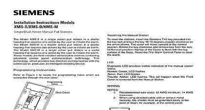
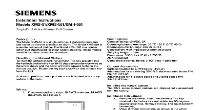
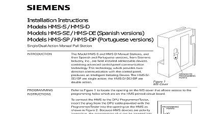
Single Dual Action Manual Pull Stations Model XMS S is a single action pull station in a plastic that requires one action by the user to initiate the alarm Model XMS D is a double action pull station in a plastic that requires two actions by the user to initiate an alarm Model XMS M is a single action pull station in a metal that requires one action by the user to initiate the alarm models are field installed addressable devices containing control panel communication This which provides two direction communication with the panel produces an Intelligent Initiating Device Instructions to Figure 1 to locate the programming holes which are through the rear cover the Manual Station reset the stations insert the Siemens T45 key provided into key lock and turn the key 10 15 degrees counter clockwise as arrow shows The cover will move upward to the normal Rotate the key clockwise and remove key from the lock Normal position the top of the Cover is flush with the top of the Base Reset the Fire Alarm Control Panel to clear alarm LED provides visible indication of the manual station Green LED flashes Red LED flashes Amber LED flashes This will happen when the Front is removed from the Manual Station Recommended wire sizes 18 AWG minimum 14 AWG When using shielded cable with or without metal the shields must be grounded solely at the of origin for example at the control panel 1 Holes Location To prevent potential damage to the DPU DO NOT an XMS to the DPU until the wire at terminal 1 is Follow the instructions in the DPU Manual P N to program the XMS to the desired address the device address on the label and attach it to the top of the base The XMS can now be installed and wired to system as shown in Figures 2 3 and 4 XMS S XMS D and XMS M manual stations operate with Desigo Fire Safety Modular Cerberus PRO Modular via the These devices can be wired in either Isolation Mode or Insensitive Mode Wiring The XMS S XMS M manual front cover has a recess pocket to pull down and locks in after the alarm is initiated The XMS D manual station an additional lever labeled HERE THEN to get to the front cover pocket to initiate the alarm 2 Mode Wiring 3 Insensitive Mode Wiring CoverLine Line From control panel orprevious addressable deviceTo next addressabledeviceLine Line Line 2Line 1From control panel or previous addressable deviceTo next addressabledeviceLine 2Line 1firealarmresources com Contents Manual station Two mounting screws One Siemens T45 key Instructions 4 the XMS Series Voltage Range 13 32 Vdc average operating current 24v 500 temperature range 32 TO 120 F 0 TO 49 C humidity range 0 to 95 RH High impact polycarbonate plastic Aluminum weight 1.0 lbs 5.50 H x 4.0 W x 1.250 D Compliant electrical boxes 2 1 2 deep 1 gang box Accessories mounted box P N S54321 F20 A1 plate for the existing SB 5R Surface mounted boxes P N plate for 4 square boxes and 2 gang boxes P N the manual station XMS series manual stations are shipped fully assembled the factory Instructions Remove the cover Insert the Siemens T45 key into the key lock and rotate key 90 degrees Remove the key The cover can be removed Make all wiring connections as shown in the wiring Figure 2 or 3 Using the two 6 32 x machine screws provided the manual station base to the electrical box Use very low torque to prevent the from becoming distorted If the base is the front cover will not operate If this remove cover and loosen the mounting accordingly Replace the cover Place the cover inside the base the key back into the lock and rotate key 90 degrees to move the cam down to lock cover in place and push cover down until is flush the top surface of the base Remove the key The station is in normal operating position To test Pull cover down to alarm position then check see if the cover is locked down Insert the key to The cover should move back to normal COVERKEY LOCK ASSYBASECOMPATIBLE ELECTRICAL1 GANG BOXLED LIGHT PIPE6 32 X1 2 SCREWS 2 PLACESCAUTION Do not overtighten the screws Overtightening may distort the Base firealarmresources com security disclaimer provides a portfolio of products solutions systems and services that security functions that support the secure operation of plants systems and networks In the field of Building Technologies this includes building and control fire safety security management as well as physical systems order to protect plants systems machines and networks against cyber threats it necessary to implement and continuously maintain a holistic state of the art concept Siemens portfolio only forms one element of such a concept are responsible for preventing unauthorized access to your plants systems and networks which should only be connected to an enterprise network the internet if and to the extent such a connection is necessary and only when security measures e g firewalls and or network segmentation are in Additionally Siemens guidance on appropriate security measures should be into account For additional information please contact your Siemens sales or visit https www siemens com global en home company topicareas portfolio undergoes continuous development to make it more secure strongly recommends that updates are applied as soon as they are and that the latest versions are used Use of versions that are no longer and failure to apply the latest updates may increase your exposure to threats Siemens strongly recommends to comply with security advisories on latest security threats patches and other related measures published among under https www siemens com cert en cert security advisories htm ID A6V11856080 enUS a A5Q00072530