Siemens ZCT-8B Zone Control Telephone Card Module, Installation Instructions

File Preview
Click below to download for free
Click below to download for free
File Data
| Name | siemens-zct-8b-zone-control-telephone-card-module-installation-instructions-5264713908.pdf |
|---|---|
| Type | |
| Size | 667.16 KB |
| Downloads |
Text Preview
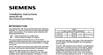
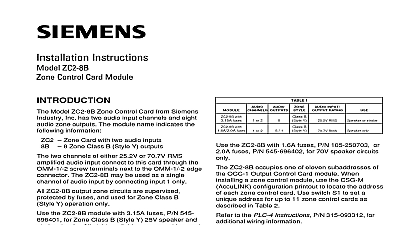
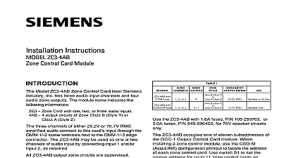
Installation Instructions ZCT 8B Control Telephone Card Module Model ZCT 8B Zone Control Telephone from Siemens Industry Inc has eight zones The name indicates the follow information Zone Control Telephone card 8 Zone Style Y telephone zone output circuits ZCT 8B connects to the telephone riser the OMM 1 Output Master module ZCT 8B zone circuits are supervised pro and for Class B Style Y zone use only module provides both dial and busy tones to five telephones can be on line at the same ZCT 8B occupies one of eleven of the OCC 1 Output Control Card When installing a zone control module the CSG M AccuLINK configuration print to locate the address of each zone control Use switch S1 to set a unique address for to zone control cards as described below additional information on the Voice System to the MXLV Manual P N 315 092036 all system power before installation battery and then AC To power up con the AC first and then the battery Remove the card from its protective bag Do touch the gold edge of the board Refer to the function section of the CSG M printout for the address of the Set the card address on switch S1 using SW1 SW4 Refer to Figure 1 for the location of S1 Refer to Table 1 for switch settings See below Industry Inc Technologies Division Park NJ 315 092105 7 1 Module Board Building Technologies Ltd Safety Security Products Kenview Boulevard Ontario 5E4 Canada open a dipswitch press down on the side of dipswitch marked OPEN To close a press down on the side of the opposite the side marked OPEN open a slide switch push the slide to the opposite the side marked ON To close a switch push the slide to the side marked ON 1 ADDR O O O O 8 O O O O O X 9 O O X O X O 10 O X O X X 11 O X X X O O ILLEGAL X X O O X O X ILLEGAL X X O X X X O ILLEGAL X X X O X X X ILLEGAL X X X X SWITCH CLOSED OR ON 0 SWITCH OPEN OR OFF NOT install the card in its edge connector ALL OMM 1 field wiring is completed and for shorts opens and other faults to the Wiring Checkout Chart Replace card in its protective bag if the wiring is not the card slot key provided in the installation with the ZCT 8B board Place the card slot key the OMM 1 edge connector for the ZCT 8B as in Figure 2 See Figure 3 for the exact of the key for this module This prevents of any other card type in the ZCT 8B Two other keys already installed in the prevent reverse installation of the card in OMM 1 edge connectors See Figure 3 the card in its card edge connector cor The components on the board must face 22 position terminal block where the wiring is Press the card firmly in place to be it is seated properly in the edge connector PIN NUMBERS KEY 1 KEY 2 KEY the Card Slot Key in the OMM 1 of User Key for ZCT 8B 2 3 RATINGS wire size wire size loop resistance 10 ohms for both wires AWG twisted pair shielded AWG twisted pair shielded VDC 9mA max VDC 300mA max P N 140 383467 of line resistor to Figure 4 wiring must comply with national and local codes all unused outputs with an EOL resistor ZONES SUPERVISED POWER LIMITED Wiring must comply with National and Local Codes Loop Resistance 10 ohnms Wire Size 18 AWG Wire Size 14 AWG Telephone Zone Connections 9 VDC 9mA max VDC 300mA max shield to negative zone terminal Refer to Wiring Specification for MXL MXL IQ MXLV Systems P N 315 092772 revision 6 higher for additional wiring information Short to Earth Ground on Terminals 1 16 will ground fault Telephone Zone Wiring Diagram 4 Industry Inc Technologies Division Park NJ 315 092105 7 Building Technologies Ltd Safety Security Products Kenview Boulevard Ontario 5E4 Canada