Siemens ZU-35 ZU-35DS ZU-35TS Dual Zone System 3 Dual-Zone Input Modules, Data Sheet

File Preview
Click below to download for free
Click below to download for free
File Data
| Name | siemens-zu-35-zu-35ds-zu-35ts-dual-zone-system-3-dual-zone-input-modules-data-sheet-3028719654.pdf |
|---|---|
| Type | |
| Size | 974.85 KB |
| Downloads |
Text Preview
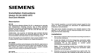
Data 3TM Input Modules ZU 35 ZU 35DS and ZU 35TS AND ENGINEER SPECIFICATIONS Complete supervision of detection circuits Class A Style D and Class B Style B Accommodates ionization photoelectric flame detectors manual stations other contact devices Alarm and Trouble light emitting diodes per zone Coast Guard Approved Model ZU 35TS UL 864 9th Edition Listed CSFM and NYC Fire Department Overviews ZU 35 dual zone input module Model ZU 35 from Fire Safety is designed to provide two 2 initiating circuits Up to 30 standard Fire Safety photoelectric detectors or detectors excluding Models DF 3 DF 3A and are supported by Model ZU 35 Additionally quantity of shorting type contact devices such manual stations and thermal detectors can be and intermixed on each initiating terminals are provided for each power limited in either NFPA Class A Style D or Class B B Industry Inc Technologies Division ZU 35DS addition to all the same features of Model ZU 35 zone is provided with a disconnect switch will disable the zone This action will cause a Trouble and a system Trouble signal until the is returned state ZU 35TS ZU 35TS is furnished with a three position test switch for each zone The switch position is in the center one side will test the zone trouble signal while the side will test a zone Alarm signal command set up is a requirement for US Coast Guard for use on marine systems and Model ZU is Coast Guard Approved Dual Zone Modules 3107 operation of a detector or shorting type device on the initiating circuit the module will into an Alarm condition initiating the start of sequential functions designed into the system functions may include sounding audible operating alarm transmitters closing doors down fans and equipment recalling and other similar functions required for and property safety addition to the system alarm a red Alarm light diode LED on the face of the dual zone will be illuminated for that particular circuit A Trouble command on either circuit will be similarly annunciated with a LED one for each circuit module supplies a current limited output signal the circuit in Alarm condition thus providing for of supplementary modules or dual zone module which occupies one 1 space in the System 3 rail structure is via a 10 pin plug and harness dual zone module Model ZU 35 35DS 35TS Underwriters Laboratories Inc Listed and FM and Humidity Range are UL 864 9th Edition Listed for indoor dry within a temperature range of 120 3 to 32 3 0 2 and at a relative of 93 2 at a temperature of 90 3 Ratings Current Current Current 23.5VDC for Ordering Dual zone module module Off zone switch module momentary and Alarm switches Approved Lb Kg Lb 0.45 Kg Lb 0.45 Kg Industry Inc Technologies Division Diagram Typical configuration for A Style D 3H H A3H B3H 11T 3P I 3RP 315 086591 3P with with The Identifier is ZU 35 35DS 35TS A Style D Initiating Circuits Total zone initiating circuit resistance 36 ohms max 9 ohms per line Unused spare zones must have end of lease device connected See individual detector for actual terminal numbers Maximum of 30 any combination of those listed on table at the right are allowed per circuit may use optional detector remote lamp detector relay as indicated on the detector instructions Industry Inc Technologies Division Diagram Typical configuration for B Style B 3H H A3H B3H 11T 3P I 3RP 315 086591 3P with with The Identifier is ZU 35 35DS 35TS B Style B Initiating Circuits Total zone initiating circuit resistance 36 ohms max 9 ohms per line Unused spare zones must have end of lease device connected See individual detector for actual terminal numbers Maximum of 30 any combination of those listed on table at the right are allowed per circuit may use optional detector remote lamp detector relay as indicated on the detector instructions This marketing data sheet is not intended to be used for system design or installation purposes the most up to date information refer to each product installation instructions Industry Inc Technologies Division Safety Fernwood Road Park NJ 07932 973 593 2600 908 547 6877 www SBT Siemens com FIS in U S A Safety Kenview Boulevard Ontario 5E4 Canada 905 799 9937 905 799 9858 2011 sheet dated 8 05 1