Silent Knight 5499 9A Distributed Power Module Manual

File Preview
Click below to download for free
Click below to download for free
File Data
| Name | silent-knight-5499-9a-distributed-power-module-manual-8302657941.pdf |
|---|---|
| Type | |
| Size | 1.33 MB |
| Downloads |
Text Preview
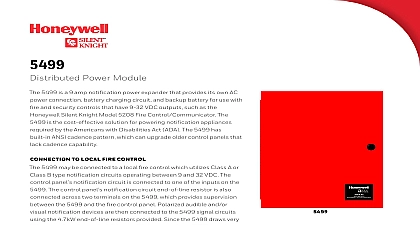
MODEL 5499 Power Module 151253 Rev N ECN 17 0298 and Manual 1 1 2 Requirements 1 3 Overview 2 Descriptions and Electrical Ratings 2 Signal Input Terminals 2 Notification Appliance Circuit Terminals 3 4 5 Mounting 5 Preventing Water Damage 5 Wire Routing 5 Current Requirements Standby and Alarm 6 Current Drawn From Host Panel 6 Current Drawn from Battery 6 Connecting the 5499 to a Control Panel 9 Common Trouble Relay 9 Notification Appliance Wiring 10 Class A Supervised Wiring 10 A Output Notification Circuits 10 A Supervised Input Circuits 10 Class B Supervised Wiring 11 B Output Notification Circuits 11 B Supervised Input Circuits 12 Ground Fault Detection Enable Disable Jumper 12 Battery Connection 12 DIP Switch Settings 13 Selecting the Standard Input Output Configurations 13 Input Output Configurations That Select ANSI Temporal Coded Outputs 14 Selecting Synchronized Output Configurations 15 Selecting Synchronized Faraday Configurations 15 Selecting Synchronized Gentex Configurations 16 Selecting Synchronized System Sensor Configurations 16 Selecting Synchronized Wheelock Configurations 16 Selecting Synchronized AMSECO Configurations 17 Setting the Loss of AC Delay 17 Distributed Power Module Installation Manual Setting the Auxiliary Output 17 5 Applications 18 Notification Power Applications 18 Non Resettable Power Application 20 Door Holder Application 21 6 21 21 Conditions 22 Earth Fault Resistance 23 Removing and Replacing the Control Panel 23 Removing the Control Panel 23 Replacing the Control Panel 24 A Listed Notification Appliances 26 Notification Appliances 26 Fire Product Warranty and Return Policy Warranties and Limitation of Liability 1 5499 is a notification appliance circuit and auxiliary power expander that provides up to 9 amps of filtered volt power for powering notification appliances and auxiliary devices The 5499 provides its own AC power battery charging circuit and battery connections Used with security and fire alarm control panels 5499 enables you to connect and distribute power to many more devices than your panel may normally allow Configurations 5499 has two optically isolated signaling inputs that provide the signal connection from the main panel to the 5499 see Section 3.2 for more details Configurations 5499 has four power limited notification appliance circuits that can be configured in various of Class A and Class B circuits see Section 3.3 for details Power Configurations 5499 has a dedicated power limited auxiliary output that can be configured in two different ways The output can either be non resettable always on or configured to switch off during the AC power to conserve the battery standby power When the auxiliary power is configured to switch off there is 30 second delay before the auxiliary power is turned off after the AC power fails see Section 4.8.4 for C Trouble Relay 5499 includes a general trouble relay that will de energize for any trouble situation see Section 4.4.1 details Fault Detection 5499 monitors for earth faults to the system power or system ground When detected the system the trouble relay and the input supervision relays see Section 5.2 for details Temporal Code 5499 provides two configuration options that will drive outputs with the ANSI temporal code if the are on constantly see Section 4.8.1 for details Synchronized appliances 5499 provides configuration options that will eliminate the need for synchronized modules when using Faraday Gentex System Sensor or Wheelock synchronization appliances 2 Requirements installed in accordance with NFPA 70 and NFPA 72 standards the 5499 can be connected to UL Listed 5499 is also listed to meet UL 864 UL 2572 and power limiting requirements 5499 is compatible with any UL listed control unit utilizing reverse polarity supervised notification circuits using 24 VDC regulated outputs 3 Overview output circuit is rated at 3 amps DO NOT OVERLOAD Overloading a circuit will cause it to shut down limit The circuit will automatically reset once you remove the overload condition Descriptions and Electrical Ratings