Silent Knight 5865-3 5865-4 Remote LED Annunciator Manual

File Preview
Click below to download for free
Click below to download for free
File Data
| Name | silent-knight-5865-3-5865-4-remote-led-annunciator-manual-6578324910.pdf |
|---|---|
| Type | |
| Size | 679.53 KB |
| Downloads |
Text Preview
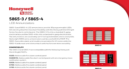
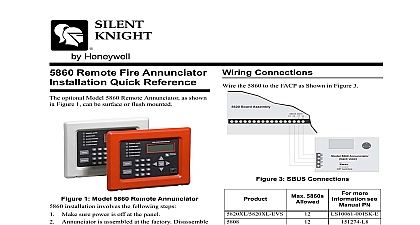
Silent Honeywell and 5865 4 Installation 2 lists the operating specifications for the and 5865 4 2 5865 3 and 5865 4 Specifications Line Resistance Alarm Current Current Voltage Temperature mA mA VDC to 49 C to 120 F Use Only Limited following instruction are a quick reference refer to the control panel installation for detailed system information 5865 3 and 5865 4 are LED Annunciators provide you with 30 programmable LED red 15 yellow 5865 connects to the panel the SBUS the 5865 3 or 5865 4 Installation and wiring of these devices must be in accordance with NFPA 72 and local the wiring as shown in Figure 1 See Table 1 1 Wire Connections Terminals 1 5865 3 or 5864 4 Connection to the FACP 151088 5865 3 and 5865 4 Installation Instructions the Device Address to Figure 2 to set the DIP switches to the address Place the 5865 3 into the 3 gang electrical See Figure 3 Box Plate 3 5865 3 Mounting Place cover plate over the top of the 5865 3 align the holes See Figure 3 the six cover plate screws into six holes on the 3 gang electrical box Screw the six cover plate screws all the way until the cover plate fits firmly against the and the electrical box Do Not over the 5865 4 5865 4 mounts into a standard 4 gang box the same procedure as used for mounting 5865 3 The 5865 4 uses 8 cover plate screws 151088 Rev C 2 Setting the Device Address the 5865 3 5865 3 mounts into a standard 3 gang box these steps to mount the 5864 3 Make sure that the 5865 3 is properly wired the control panel See Figure 1