SIlent Knight 5883 Relay Interface Board Manual

File Preview
Click below to download for free
Click below to download for free
File Data
| Name | silent-knight-5883-relay-interface-board-manual-8345219067.pdf |
|---|---|
| Type | |
| Size | 884.67 KB |
| Downloads |
Text Preview
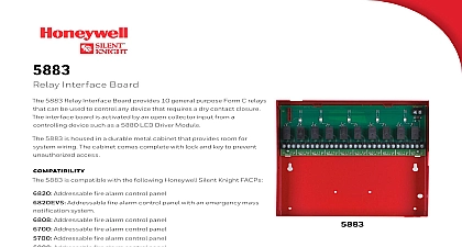
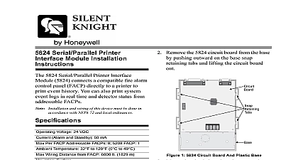
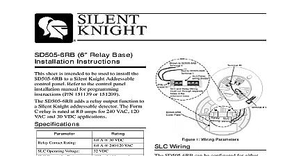
5883 Interface Board Installation and wiring of this device must be done accordance with NFPA 72 and local ordinances All wiring is supervised and power limited following instruction describe how to install 5883 to a Silent Knight Addressable fire panel Refer to the control panel manual P N 151139 or 151209 for instructions 5883 is a relay interface board that has 10 purpose Form C relays that can be used activating voice evacuation elevator recall or fan cut off as examples relay is activated by an open collector from a controlling device such as a 5880 1 lists the electrical physical and specifications of the Model 5883 1 Model 5883 Specifications Parameter Temperature Trigger Voltage C Relay Voltage 120 F 49 C 26.04 cm 26.35 cm 7.94 cm VDC 30 VDC or 250 VAC VDC 420 mA max indoor use only 1 Wire Routing Example 1 4 spacing must be maintained between and Low voltage circuits as well as power limited and non power circuits When using a combination of power limited non power limited circuits you must an unused relay in between to a 1 4 spacing 151194 5883 Installation Instructions the 5883 to Aux power the power terminals of the 5883 to a 24 power supply as shown in Figure 2 Power Using Circuits 5883 can use aux power from any 24 VDC The following describes how to use the circuits as the auxiliary power source Connect the aux power wires to the Flexput using terminals as positive terminals as negative power See 3 2 Auxiliary Power Connections Auxiliary power is supplied by a Regulated UL power supply for Fire Protective Signalling 3 Flexput Auxiliary Power Output Configure the auxiliary power output for output through programming Refer the control panel installation manual 151139 151209 151194 Input Connector 5883 12 Pin input connector P1 plugs onto any of the 12 pin connectors on the Wiring 10 on board relays are all Form C relays 4 is an example of how the relays can be be wired within feet of the 5883 and in conduit following table list the pin outs for the P 1 connector on the 5883 Relay 1 Relay 2 Relay 3 Relay 4 Relay 5 Relay 6 Relay 7 Relay 8 Relay 9 Relay 10 VDC Used 4 Relay Wiring Example 151194 5883 Installation Instructions the cabinet as shown in Figure 5 Install 5883 circuit board as shown in Figure 6 5 Cabinet Installation 6 Circuit Board Mounting 151194 Rev A