Silent Knight IDPcontrol6 isheet

File Preview
Click below to download for free
Click below to download for free
File Data
| Name | silent-knight-idpcontrol6-isheet-7140238965.pdf |
|---|---|
| Type | |
| Size | 884.02 KB |
| Downloads |
Text Preview
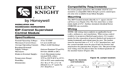
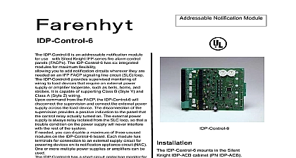
NOTICE This manual should be left with the owner of this equipment DESCRIPTION IDP Control 6 Six Circuit Supervised Control is intended for use in an intelligent alarm sys Each module is intended for switching applications AC or DC which require wiring supervision A SLC input is used for all modules Each module its own address A pair of rotary code switches is to set the address of the first module from 01 to 94 remaining modules are automatically assigned to the five higher addresses Provisions are included for a maximum of three unused modules to release addresses to be used elsewhere Each module also panel controlled green LED indicators The panel can the LEDs to blink latch on or latch off In order synchronize strobes horn strobes and speaker strobes SYNC 1 accessory card sold separately must be used the IDP Control 6 See the SYNC 1 installation for details on how to install 1 Terminal 11 4 32mm offs Large Shunts Machine Screws Short Power Jumpers Small Shunts Nuts Long Power Supply Jumper 47k Ohm of Line EOL Relay AND MAINTENANCE Six Circuit Control Module mA mA assumes all six relays have switched and all six LEDs on to 120 0 to 49 to 55 to 85 Non condensing H x 5.8 W x 1.25 D Cabinet and chassis AWG Operating Voltage 15 32 VDC Current Current Range Gauge NAC Circuit Resistance Rating Per Circuit 63 W 70.7 VAC 50 W 25 VAC INSTALLING the modules will be installed in an existing operational inform the operator and local authority that the will be temporarily out of service Disconnect the to the control panel before installing the modules system contains static sensitive components Always yourself with a proper wrist strap before handling circuits so that static charges are removed from the The housing cabinet should be metallic and suit grounded Ohms 1 RATING VOLTAGE DESCRIPTION A A A A A A A A A A VDC VDC VDC VDC VDC VDC VAC VAC VAC VAC L R 5ms L R 2ms PF 35 PF 35 PF 35 PF 35 relay switch contacts are shipped in the standby state open state but may have transferred to the activated closed during shipping To ensure that the switch contacts are in their correct state modules must be made to communi with the panel before connecting circuits controlled by the module 2 Short Circuit Protection UL 864 9th Edition Requirements TO USERS INSTALLERS AUTHORITIES HAVING JURISDICTION AND OTHER INVOLVED PARTIES product incorporates field programmable software In order for the product to comply with requirements in the Standard for Units and Accessories for Fire Alarm Systems UL 864 certain programming features or options must be limited to spe values or not used at all as indicated below Feature or Option Settings Permitted in UL 864 in 864 Y N short circuit protection a single power supply is by multiple NACs or Disable short protection short circuit protection when a single supply is shared by multiple NACs circuit protection can be disabled only a power supply is not shared by multiple STEPS Cabinet Mounting a clean dry area mount the backbox using the four holes in the back surface of the cabinet Figure 3 module has terminals for connection to an external circuit for powering devices on its NAC Each must be power limited and its voltage current lim must be at or below those specified in Table 1 There a short circuit protection monitor for each module This provided to protect the external power supply against circuit conditions on the NAC on Board Small shunt in A B select position Shipped in Class B position remove shunt for Class A Large shunts on Enable Power Supply Monitors Large shunts on Disable Short Circuit Protection Large shunts on Sync Generator REQUIREMENTS ensure proper operation this module shall be con to a compatible Silent Knight system control panel following is a description of the IDP Control 6 framework One or two IDP Control 6 modules can be installed in a IDP ACB cabinet IDP ACB cabinet has a built in chassis that will ac one or two IDP Control 6 modules 2 Typical mounting hole locations Module Installation There are two methods for installing a module in the position of a chassis Method one is for installa of a rear module only when no module will be in in front of it Refer to Figure 3 for instructions two is for installation of a rear module when module will be installed in the chassis position front of it Refer to Figures 4a and 4b for method All necessary screws and standoffs are supplied the modules 1 IDP ACB Cabinet front IDP Control 6 module positions of each chassis offset below the rear IDP Control 6 module positions that all of the status indicators are visible For cabinet refer to the IDP ACB instruction manual 3 Installation of rear module only method one 1 Insert the bottom of the IDP Control 6 module into a rear slot on the chassis 2 Carefully swing the upper edge of the board towards the back of the chassis until it the two standoffs 3 Align two 4 40 screws with the two standoffs tighten 4 Address and wire the modules according to the in this manual steps in Figures 4a and 4b describe and illustrate mod installation when the rear chassis position and the posi in front of it will be filled Front position installation possible only if the rear position is filled with a module 4a Installation of IDP Control 6 module in a chassis position method two 1 Insert the bottom edge of the IDP Control 6 down into a rear slot of the chassis 2 Carefully swing the upper edge of the board the back of the chassis until it touches short standoff attached to the chassis 3 Align the long standoff with the short standoff tighten 4b Installation of IDP Control 6 module in chassis position 1 Insert the bottom edge of the IDP Control 6 down into a front slot of the chassis 2 Carefully swing the upper edge of the board the back of the chassis until it touches 11 4 31.75mm standoffs installed on the module 3 Align two 4 40 screws with the two standoffs tighten 4 Address and wire the modules according to the in this manual All wiring must conform to applicable local ordinances and regulations Install module wiring in accordance with the job draw and appropriate wiring diagrams All wiring to the IDP Control 6 is done via terminal In order to properly make electrical connec strip approximately 1 4 of insulation from the of wire sliding the bare end of the wire under the plate screw Set the address on the modules per the job drawing the rotary code switches to set the address of the module between 01 and 94 select Class B operation install the J1 Shunt The re modules are automatically assigned to the next higher addresses For example if the base address is set to 28 the next five modules will be ad to 29 30 31 32 and 33 select Class A operation remove the J1 Sh