Silent Knight IDPheat isheet

File Preview
Click below to download for free
Click below to download for free
File Data
| Name | silent-knight-idpheat-isheet-9367018542.pdf |
|---|---|
| Type | |
| Size | 678.95 KB |
| Downloads |
Text Preview
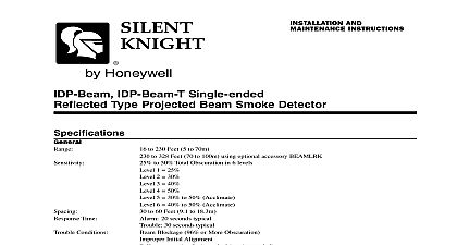
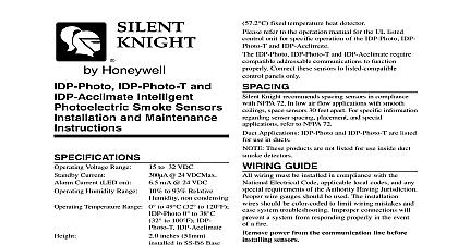
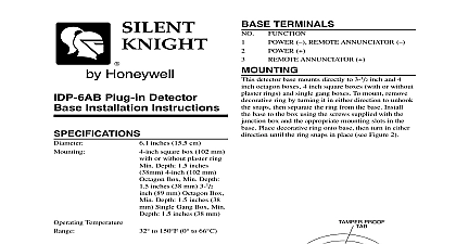
GENERAL DESCRIPTION IDP Heat IDP Heat ROR and IDP Heat HT are sensors that utilize a state of the art thermistor circuit for fast response These sensors are to provide open area protection with 50 foot capability Model IDP Heat is a fixed temperature with 135 F fixed temperature alarm IDP Heat is a rate of rise temperature sensor with 135 F temperature alarm Model IDP Heat HT is a high sensor with 190 F fixed temperature alarm LEDs on each sensor light to provide a local visible indication Remote LED annunciator capability is as an optional accessory Part No RA400Z IDP Heat IDP Heat ROR and IDP Heat HT compatible addressable communications to properly Connect these sensors to listed control panels only GUIDE wiring must be installed in compliance with the Electrical Code applicable local codes and the Having Jurisdiction Proper wire gauges should used The installation wires should be color coded to wiring mistakes and ease system troubleshooting connections will prevent a system from properly in the event of a fire power from the communication line before sensors Wire the sensor base supplied separately per the diagram see Figure 1 Set the desired address on the sensor address switches Figure 2 Install the sensor into the sensor base Push the sensor into base while turning it clockwise to secure it in place After all sensors have been installed apply power to control unit and activate the communication line Test the sensor s as described in the TESTING of this manual RESISTANCE sensor base includes a tamper proof feature which activated prevents removal of the sensor without the of a tool See the installation instruction manual for sensor base for details in using this feature testing notify the proper authorities that the is undergoing maintenance and will temporarily out of service Disable the system to prevent unwanted sensors must be tested after installation and thereafter Testing methods must satisfy the Having Jurisdiction AHJ Sensors offer performance when tested and maintained in with NFPA 72 and Maintenance for IDP Heat IDP Heat and IDP Heat HT Intelligent Temperature Sensors inches 155mm in IDP 6AB inches 104mm in B501 inches 51mm ounces 137 gm Temperature to 100 to 8 and IDP Heat ROR to 150 to IDP Heat HT Humidity Range 10 to 93 Relative Range Current Current Temperature Rating Detection Non condensing flanged base flange less base to 32 Volts DC Peak 24 VDC mA 24 VDC 57 IDP Heat IDP Heat ROR 190 IDP Heat HT to greater than IDP Heat ROR sensor must be installed in compliance with the panel system installation manual The installation meet the requirements of the Authority Having AHJ Sensors offer maximum performance installed in compliance with the National Fire Association NFPA see NFPA 72 installing sensors please read the system wiring installation manual thoroughly This manual provides information on sensor spacing placement and special applications Copies of these manuals available from Silent Knight Do Not Loop Wire Under Terminal 1 or 2 Wire To Provide Supervision of Connections A OPTIONAL WIRING 1 Test Magnet Model No M02 04 optional 1 Place the optional test magnet against the cover the magnet test area as shown in Figure 3 to the test feature part number K200 07 00 2 The LEDs should latch on within 10 seconds alarm and annunciating the panel 3 Reset the detector at the system control panel Direct Heat Method Hair dryer of 1000 watts 1 From the side of the detector direct the heat toward sensor Hold the heat source about 6 inches 15 away to prevent damage to the cover during 2 The LEDs on the detector should light when the at the detector reaches the alarm If the LEDs fail to light check the power the detector and the wiring in the detector base 3 Reset the detector at the system control panel that fail these tests should be cleaned as described MAINTENANCE and retested If the detectors still these tests they should be returned for repair 0 0 2 3 Views showing position of test magnet MAGNET Before cleaning notify the proper authorities that the system is undergoing maintenance and therefore the system temporarily be out of service Disable the loop or system undergoing maintenance to prevent unwanted alarms is recommended that the sensor be removed from its mounting base for easier cleaning and that sensors be cleaned at once a year Use a vacuum cleaner to remove dust from the sensing chamber 4 Meridian Circle Grove MN 55369 4927 800 328 0103 763 493 6475 2005 Silent Knight refer to insert for the Limitations of Fire Alarm Systems Statement device complies with part 15 of the FCC Rules Operation is subject to the following two conditions 1 This device may not cause harmful and 2 this device must accept any interference received including interference that may cause undesired operation equipment has been tested and found to comply with the limits for a Class B digital device pursuant to Part 15 of the FCC Rules limits are designed to provide reasonable protection against harmful interference in a residential installation This equipment uses and can radiate radio frequency energy and if not installed and used in accordance with the instructions may cause interference to radio communications However there is no guarantee that interference will not occur in a particular installation If equipment does cause harmful interference to radio or television reception which can be determined by turning the equipment off and the user is encouraged to try to correct the interference by one or more of the following measures Reorient or relocate the receiving antenna Increase the separation between the equipment and receiver Connect the equipment into an outlet on a circuit different from that to which the receiver is connected Consult the dealer or an experienced radio TV technician for help