Silent Knight IDPmonitor isheet

File Preview
Click below to download for free
Click below to download for free
File Data
| Name | silent-knight-idpmonitor-isheet-7038946215.pdf |
|---|---|
| Type | |
| Size | 746.00 KB |
| Downloads |
Text Preview
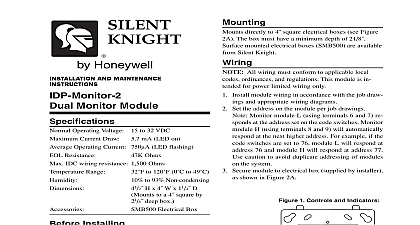
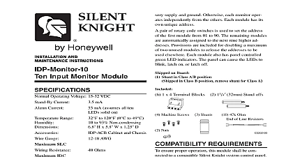
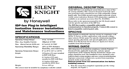
Mounting IDP Monitor mounts directly to 4 square electri boxes see Figure 2A The box must have a mini depth of 21 Surface mounted electrical boxes are available from Silent Knight All wiring must conform to applicable local ordinances and regulations This module is in for power limited wiring only Install module wiring in accordance with the job draw and appropriate wiring diagrams Set the address on the module per job drawings Secure module to electrical box supplied by installer shown in Figure 2A 1 Controls and Indicators 865 6 7 8 9 2A Module mounting For UL Listed security installations the IDP Monitor be mounted within the control panel enclosure 2B 0 E N S 0 N E S D D R E S S AND MAINTENANCE Module Ohms mA LED on Ohms to 120 0 to 49 to 93 Non condensing H x 4 W x 11 D to a 4 square by deep box Electrical Box Operating Voltage 15 to 32 VDC Current Draw Operating Current 375 LED flashing Resistance IDC resistance Range Installing information is included as a quick reference installa guide Refer to the control panel installation manual detailed system information If the modules will be in an existing operational system inform the and local authority that the system will be tem out of service Disconnect power to the control before installing the modules This manual should be left with the owner of this equipment Description IDP Monitor Module is intended for use in intel two wire systems where the individual address of module is selected using the built in rotary switches provides either a Class A or Class B fault tolerant initi device circuit IDC for normally open contact fire and supervisory devices or either normally open or closed security devices The module has a panel LED indicator Requirements ensure proper operation this module shall be con to a compatible Silent Knight system control panel available from Silent Knight 3 Typical 2 wire initiating circuit configuration NFPA Style B NEXT NUMBER OF UL LISTED CONTACT CLOSURE MAY BE USED DO NOT MIX FIRE INITIATING SUPERVISORY OR DEVICES ON THE SAME MODULE K EOL 865 6 7 8 9 PANEL OR DEVICE MODULES TO LISTED COMPATIBLE KNIGHT CONTROL PANELS ONLY LINE CIRCUIT SLC VDC MAX PAIR RECOMMENDED DEVICE CIRCUIT IDC NFPA STYLE B LIMITED 230A MAX 12 VDC MAX CONTACT CLOSURE DEVICES PER INSTALLATION INSTRUCTIONS LOSS OPTIONAL CONNECTION FOR WHICH SUPPORT THIS FEATURE WIRING SHOWN IS SUPERVISED AND POWER LIMITED 4 Typical 4 wire fault tolerant initiating circuit configuration NFPA Style D NEXT NUMBER OF UL LISTED CONTACT CLOSURE MAY BE USED DO NOT MIX FIRE INITIATING SUPERVISORY OR DEVICES ON THE SAME MODULE PANEL OR DEVICE MODULES TO LISTED COMPATIBLE SILENT KNIGHT CONTROL PANELS ONLY RESISTOR INTERNAL AT 8 9 LINE CIRCUIT SLC VDC MAX PAIR RECOMMENDED LOSS OPTIONAL CONNECTION PANELS WHICH SUPPORT THIS FEATURE CONTACT CLOSURE DEVICES PER INSTALLATION INSTRUCTIONS WIRING SHOWN IS SUPERVISED AND POWER LIMITED 5 Typical 2 wire initiating circuit configuration for security systems with alarm versus short capability For UL Listed security installations the IDP Monitor must be mounted within the control panel enclosure NEXT NUMBER OF UL LISTED CONTACT CLOSURE MAY BE USED DO NOT MIX FIRE INITIATING SUPERVISORY OR DEVICES ON THE SAME MODULE PANEL OR DEVICE MODULES TO LISTED COMPATIBLE KNIGHT CONTROL PANELS ONLY SERIES RESISTOR K EOL LINE CIRCUIT SLC VDC MAX PAIR RECOMMENDED DEVICE CIRCUIT IDC NFPA STYLE B LIMITED 230A MAX 12 VDC MAX CONTACT CLOSURE DEVICES PER INSTALLATION INSTRUCTIONS LOSS OPTIONAL CONNECTION FOR WHICH SUPPORT THIS FEATURE WIRING SHOWN IS SUPERVISED AND POWER LIMITED Meridian Circle Grove MN 55369 4927 800 328 0103 763 493 6475 2006 Silent Knight