Silent Knight IDPpductR isheet

File Preview
Click below to download for free
Click below to download for free
File Data
| Name | silent-knight-idppductr-isheet-7135240986.pdf |
|---|---|
| Type | |
| Size | 1.21 MB |
| Downloads |
Text Preview
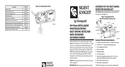
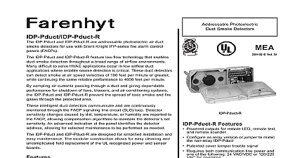
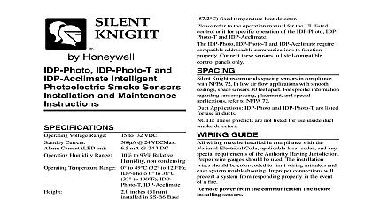
Figure 14 Testing detector alarm Ratings SPST A 30 VDC A 277 VAC 75 power factor VA 249 VAC 0.4 power factor HP 120 VAC HP 240 VAC A 30 VDC resistive switching current for auxiliary contact must be 100 mA DC 5 VDC Requirements using no accessories supply voltage standby current alarm current response time up time VDC VAC 50 60 Hz VAC 50 60Hz VAC 50 60Hz mA mA to 10 Sec Sec mA RMS mA RMS to 10 Sec Sec mA RMS mA RMS to 10 Sec Sec mA RMS mA RMS to 10 Sec Sec Specifications Requirements for System Control Panels are a limited number of devices that can have their programmed to illuminate The actual number devices is determined by the control panel and its to supply LED current Refer to the Control Panel Manual for details Current Loads at 24 VDC LED Remote Test Remote Test Filters Test Magnet Photo Insect Screen End Cap for Plastic Sampling Tube mA mA mA mA Max mA Max mA Max End Cap for Metal Sampling Tubes Photoelectric Sensor Board Power Board w relay No Meridian Circle Grove MN 55369 4927 800 328 0103 763 493 6475 2005 Silent Knight refer to insert for the Limitations of Fire Alarm Systems keep your equipment in excellent working order ongoing maintenance is required per the manufacturer recommendations and UL and NFPA At a minimum the requirements of Chapter 7 of NFPA 72 the National Fire Alarm Code shall be followed A preventative maintenance should be arranged through the local manufacturer representative Though smoke detectors are designed for long life they may fail at any Any smoke detector fire alarm equipment or any component of that system which fails shall be repaired or replaced as soon as possible Statement device complies with part 15 of the FCC Rules Operation is subject to the following two conditions 1 This device may not cause harmful and 2 this device must accept any interference received including interference that may cause undesired operation equipment has been tested and found to comply with the limits for a Class B digital device pursuant to Part 15 of the FCC Rules limits are designed to provide reasonable protection against harmful interference in a residential installation This equipment generates and can radiate radio frequency energy and if not installed and used in accordance with the instructions may cause harmful interference radio communications However there is no guarantee that interference will not occur in a particular installation If this equipment does harmful interference to radio or television reception which can be determined by turning the equipment off and on the user is to try to correct the interference by one or more of the following measures Reorient or relocate the receiving antenna Increase the separation between the equipment and receiver Connect the equipment into an outlet on a circuit different from that to which the receiver is connected Consult the dealer or an experienced radio TV technician for help installing detectors please thoroughly read the Guide for Proper Use of Smoke Detectors in Duct which provides detailed information on spacing placement zoning wiring and special Copies of this manual are available from National Electrical Manufacturers Association L Street NW Washington DC 20037 NFPA 72 and 90A should also be referenced for information This manual shall be left with the owner user this equipment This detector must be tested and regularly following NFPA 72 requirements detector should be cleaned at least once a year OF THE DUCT SMOKE HOUSING KIT IDP Pduct R Duct Smoke Detector consists of the items See Figure 1 1 Exploded view of duct smoke components TUBE HOLES TUBE BOARD STRIP BOARD MOUNTING Of The Duct Smoke Detector Complete duct smoke detector assembly with sensor Two 10 x 11 sheet metal mounting screws Two sampling tube filters One test magnet Drilling template Two foam gaskets Four 6 self tapping mounting screws for the sampling tube and optional exhaust tube extension One sampling tube end cap One plastic sampling tube One 8 self tapping screw for plastic sampling tube A detector sensor board DOES NOT need to ordered separately For ducts over 11 0.46m feet longer sampling must be ordered to complete the installation They be the correct length for the width of the duct where will be installed See Table 1 on page 3 to determine sampling tube required for different duct widths AND INSTRUCTIONS INTELLIGENT SMOKE DETECTOR EXTENDED SPEED RANGE DESCRIPTION HVAC system supplies conditioned air to virtually area of a building Smoke introduced into this air system is distributed to the entire building Smoke designed for use in air duct systems are used to the presence of smoke in the duct IDP Pduct R air duct smoke detector is a detector This smoke detection method with an efficient housing design that samples passing through a duct and allows detection of a hazardous condition When sufficient smoke sensed an alarm signal is initiated at the fire control monitoring the detector and appropriate action can taken to shut off fans blowers and change over air systems etc This can prevent the distribution or can isolate toxic smoke and fire gases throughout the served by the duct system LEDs on each detector may illuminate if by the system control panel to provide local alarm indication There is also a remote alarm for use with auxiliary devices The IDP Pduct R remote test capability with the RTS451 RTS451KEY Test Station IDP Pduct R incorporates a cover tamper feature the cover is removed for more than 20 minutes unit loses communication at the panel a trouble is at the panel and the alarm relay switches states shutting down fans dampers and blowers In case when the sensor is removed or when there is no to the unit only a trouble is indicated at the panel relay does not work any longer OF DUCT DETECTORS National Fire Protection Association has established DUCT DETECTORS MUST NOT BE USED AS SUBSTITUTE FOR OPEN AREA DETECTOR as a means of providing life safety Nor they a substitute for early warning in a building fire detection system is strongly recommended that the user read NFPA 90A 72 and 101 device will not operate without electrical power situations may cause an interruption of power The safeguards should be discussed with your local protection specialist device will not sense smoke unless the ventilation is operating order to function properly this detector must be according to the instructions Do not exceed the or ambient specifications or the detector will function properly This detector must be protected the elements SEQUENCE 1 Verify duct air flow direction and velocity 2 2 Drill the mounting holes 2 2.1 Install the sampling tube for ducts less than 11 0.46m wide 2 3 Secure the detector housing to the duct 3 the sampling tube for ducts greater than 4 feet 0.46m wide 3 4.1 Installation for ducts greater than 11 feet but less than 8 feet 2.4m wide 3 4.2 Installation for ducts more than 8 feet wide 4 5 the filters 4 6 Field wiring 4 7 Perform detector check