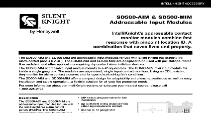
Silent Knight SD500-AIM Addressable Input Module and SD500-MIM Addressable Mini-Input Module Manual

File Preview
Click below to download for free
Click below to download for free
File Data
| Name | silent-knight-sd500-aim-addressable-input-module-and-sd500-mim-addressable-mini-input-module-manual-3749680251.pdf |
|---|---|
| Type | |
| Size | 1.30 MB |
| Downloads |
Text Preview
Input Module and Mini Input Module Instructions following instructions are a quick reference refer to the control panel installation P N 151139 151274 151280 151295 or 151302 for detailed system the SD500 AIM MIM and wiring of these devices must be done in with NFPA 72 and local ordinances the wiring as shown in Table 1 See Figure 1 or Figure 2 1 Wire Connections or SLC Terminals A B out out IN CLASS A ONLY Only IN N O Contact N O Contact of Loop A of Loop B 2 lists the operating specifications for the and the SD500 MIM 2 SD500 AIM and SD500 MIM Specifications Line resistance Alarm device in alarm 46 mA for two in alarm Voltage mA for each addi device in V 2 SD500 AIM and SD500 MIM Specifications Temperature use only to 49 C to 120 F for Earth Ground Fault is 0 for all 1 Class B Wiring the SD500 AIM SD500 MIM 151071 Input Module and SD500 MIM Mini Input Module Installation Instructions LED 2 Class A Wiring the SD500 AIM the SD500 AIM the SD500 AIM into a double gang box shown in Figure 3 the SD500 MIM the SD500 MIM into a single gang box Figure 1 and Figure 3 4 Setting the Device Address The dip switch settings shown in Figure 4 apply to the also 3 Mounting the SD500 AIM and SD500 MIM the Devices Address range of valid addresses is 1 127 0 is an address Refer to Figure 4 to set the dip to the desired address 2008 Honeywell International Inc PN 151071 Rev G Meridian Circe Suite 100 Grove MN 55369 4927 or 800 328 0103 763 493 6475


