Silent Knight SD500-LED LED Driver Module Manual

File Preview
Click below to download for free
Click below to download for free
File Data
| Name | silent-knight-sd500-led-led-driver-module-manual-0834961725.pdf |
|---|---|
| Type | |
| Size | 758.56 KB |
| Downloads |
Text Preview
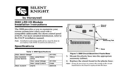
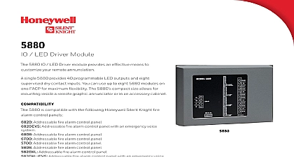
Caution of the circuit board components are extremely sensitive static electricity The following procedures reduce the of damaging components with static electricity Before handling the circuit board in any way discharge body static electric charge by touching a grounded Wear a grounding wrist strap if one is available Do not remove parts from their antistatic containers or until you are ready to install them When removing a board from a cabinet immediately place it in an bag or container When handling a circuit board hold it by its edges and touching the circuitry Do not slide circuit boards over any surface Avoid having plastic vinyl and foam in your work area Limiting your movement during installation and or reduces static electricity LED Driver Module Instructions following are instructions on how to install and the SD500 LED to a Silent Knight control panel SD500 LED is a LED driver module capable of 80 LEDs which connects to the SLC loop on Silent Knight addressable control panel to 40 SD500 LED modules can be used per SLC with a maximum of 100 SD500 LED modules system Power Max Max Current Temperature mA mA mA mA mA to 49 C 32 to 120 F use only Instructions section contain instruction on how to mount the cabinet and how to insert the SD500 control board these steps to mount the cabinet Remove the control board from the cabinet See notice See also Figure 2 Mount cabinet as shown in Figure 1 Re install the control board See Figure 2 1 Cabinet Mounting 151232 Rev A Limited Installation Instructions Board Brackets Board Screws 2 Control Board Installation Instructions section contains information on how to connect SD500 LED to the main control panel and how to the LED outputs Installation and wiring of this device must be done accordance with NFPA 72 and local ordinances the SD500 LED to the Control Panel the wiring as Described in Table 1 See Fig 1 Wire Termination Control Panel 151232 Power Using Flexput SD500 LED can use aux power from any 24 source The following describes how to use the circuits as the auxiliary power source Connect the aux power wires to the Flexput using terminals as positive and terminals as negative power See Figure 3 Instructions Wiring SD500 LED has eight 12 pin connectors P N used to connect LEDs All LED outputs use common pin on each connector for LED power see 4 Current is limited through each output so series resistor is required 4 SD500 LED Output Wiring 3 Flexput Auxiliary Power Output Configure the auxiliary power output for output through programming Refer to control panel installation manual 151139 151209 151232 Installation Instructions Module ID device on a SLC loop needs a unique ID Figure 5 illustrates the ID choices 5 Module ID Settings Meridian Circle Suite 100 Grove MN 55369 4927 or 800 328 0103 763 493 6475 International Inc 151232 Rev A