Silent Knight SD505-DUCT Duct Housing & Smoke and SD505-DUCTR Duct Housing & Smoke w Relay Manual
File Preview
Click below to download for free
Click below to download for free
File Data
| Name | silent-knight-sd505-duct-duct-housing-smoke-and-sd505-ductr-duct-housing-smoke-w-relay-manual-9102768534.pdf |
|---|---|
| Type | |
| Size | 870.13 KB |
| Downloads |
Text Preview
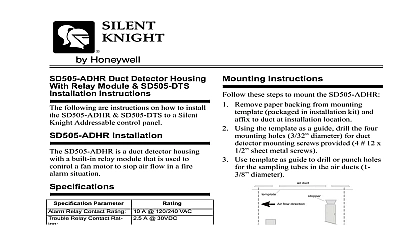
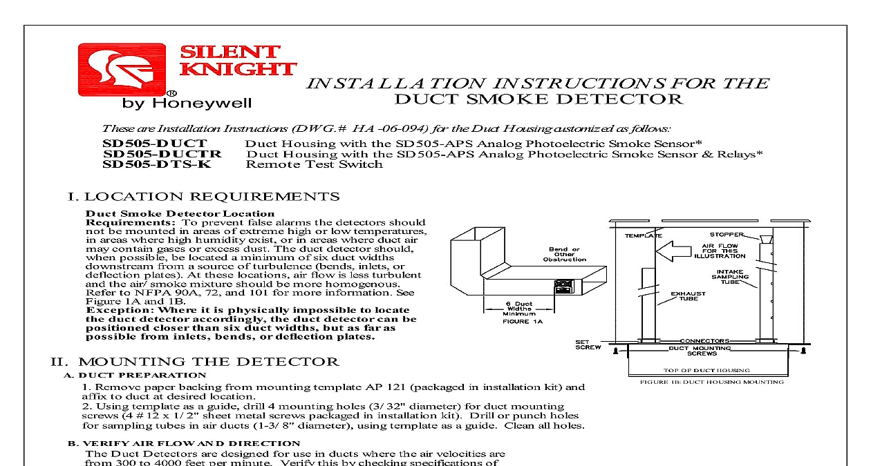
R Honeywell INSTRUCTIONS FOR THE SMOKE DETECTOR are Installation Instructions DWG HA 06 094 for the Duct Housing customized as follows Duct Housing with the SD505 APS Analog Photoelectric Smoke Sensor Duct Housing with the SD505 APS Analog Photoelectric Smoke Sensor Relays Remote Test Switch MOUNTING THE DETECTOR DUCT PREPARATION Remove paper backing from mounting template AP 121 packaged in installation kit and to duct at desired location Using template as a guide drill 4 mounting holes 3 32 diameter for duct mounting 4 12 x 1 2 sheet metal screws packaged in installation kit Drill or punch holes sampling tubes in air ducts 1 3 8 diameter using template as a guide Clean all holes OF DUCT HOUSING 1B DUCT HOUSING MOUNTING LOCATION REQUIREMENTS Smoke Detector Location To prevent false alarms the detectors should be mounted in areas of extreme high or low temperatures areas where high humidity exist or in areas where duct air contain gases or excess dust The duct detector should possible be located a minimum of six duct widths from a source of turbulence bends inlets or plates At these locations air flow is less turbulent the air smoke mixture should be more homogenous to NFPA 90A 72 and 101 for more information See 1A and 1B Where it is physically impossible to locate duct detector accordingly the duct detector can be closer than six duct widths but as far as from inlets bends or deflection plates VERIFY AIR FLOW AND DIRECTION Duct Detectors are designed for use in ducts where the air velocities are 300 to 4000 feet per minute Verify this by checking specifications of and if necessary use an Alnor Model 6000P velocity meter or to check the air velocity See Figure 2 for sampling tube to air flow direction SAMPLING TUBE ASSEMBLY See Figure 2 sampling tubes may be ordered to a desired length or in one of 3 standard lengths and cut per requirements intake sampling tube consists of a piece of steel piping with series of holes drilled the entire length of the tube and should the entire width of the duct The holes must be facing the air flow see Figure 2 The exhaust tube consists of a of steel piping approximately 7 1 2 long SAMPLING TUBES STANDARD LENGTHS duct widths of 1.0 to 2.5 duct widths of 2.5 to 5.0 duct widths of 5.0 to 10.0 Cut the intake sampling tube to the desired length Firmly insert the stopper packaged in installation kit in the end of the INTAKE sampling tube MOUNT SAMPLING TUBES See Figure 2 Sampling tube connectors are equipped with set screws which allow the tubes to be mounted only in directions shown in 2 Establish proper orientation considering airflow direction Insert intake and exhaust tubes into connectors align set screw to set screw hole in tubes and tighten firmly MOUNT THE DUCT HOUSING See Figure 1B 2 duct housing sampling tube assembly to desired location Use 4 mounting screws 4 12 x 1 2 sheet metal screws in installation kit to secure the housing to the air duct VERIFY AIR SAMPLING See Figure 3 verify proper sampling of air use a Dwyer Model 4000 differential pressure gauge or equivalent See Figure 3 for connections The pressure differential between input sampling tube and exhaust tube should be greater than of water and less than 1.2 of water Instructions P N 1700 09882 HA 06 094 Page 1 of 3 subject to change without notice September 2014 Relay Contact Rating Relay Contact Rating Voltage Power Input Current Input Current SLC Resistance Temperature Velocity Rating Ohms 100F 85 RH Non Condensing 4000 ft min 24VDC 115VAC 240VAC 30VDC Standby Alarm Ohms 100F 85 RH Non Condensing 4000 ft min ELECTRICAL INSTALLATION GENERAL INFORMATION must conform to applicable local codes ordinances and regulations these types of devices Wire the detectors according to the drawings for the particular job requirements These detectors not intended for open area protection nor should they be used for air protection Refer to NFPA 90A and NFPA 72 for general and information on Duct Smoke Detectors concerning operation installation Terminals are suitable for up to 14 gauge wire DETECTOR WIRING With power source de energized and the smoke detector not installed wire connections per engineering drawings Refer to the applicable figures below on your duct housing model number With all wiring in place install the detector head Energize the duct detector TUBE TUBE PRESSURE PRESSURE 4000 DIFFERENTIAL GAUGE OR WITH TUBING SIZE 0 RUBBER STOPPERS PART 0700 01118 3 AIR SAMPLING WIRING DIAGRAMS WIRING DIAGRAM SD505 DUCT is not a self contained sensor product is compatible only with fire alarm panels that utilize Silent Knight Digital Protocol SENSOR R USED and ALARM current should 0.55mA WIRING DIAGRAM POLARITY VOLTAGE V D C mA Standby Alarm SHUTDOWN EXAMPLE VOLTAGE LISTED PANEL TEST CONTACTS 250VAC 250VAC function only Does not reset ADDRESSABLE LOOP WIRING NEXT SENSOR RETURN CONTROL PANEL Remote Accessories as indicated above if required is not a self contained stand alone detector U L Listed Analog Addressable Fire System is required Installation Instructions P N 1700 09882 HA 06 094 Page 2 of 3 subject to change without notice September 2014 AND SD505 DTS K CONNECTIONS GND PILOT ALARM TO INSTALLATION INSTRUCTIONS HA 06 094 SILENT KNIGHT DETECTORS ARE INTENDED FOR USE WITH AIR DUCT VELOCITIES FROM 300 TO 4000 FEET PER MINUTE THIS BY CHECKING THE SPECIFICATIONS OF HVAC INSTALLATION AND IF NECESSARY USE AN ALNOR 6000P VELOCITY METER OR EQUIVALENT TO CHECK AIR VELOCITY PRESSURE DIFFERENTIAL MEASUREMENTS SHOULD BE MADE USING A DWYER PRESSURE GAGE CATALOG 3 WATER FULL SCALE TO INSURE AIR FLOW IN THIS CHAMBER THE PRESSURE DIFFERENTIAL INPUT AND EXHAUST TUBE SHOULD BE BETWEEN 0.01 AND 1.2 INCHES OF WATER DO NOT INSTALL WHERE AMBIENT TEMPERATURE EXCEEDS 100 38 TERMINALS 3,4,5,6,7,8 DO NOT USE LOOPED WIRE UNDER TERMINALS BREAK WIRE RUN TO PROVIDE SUPERVISION OF CONNECTION VDC NO NO GND PILOT ALARM SLC LED 4 E 9 H 5 Knight Control Panel OUT A Style 6 Wiring GND PILOT ALARM SLC LED Knight Control Panel OUT GND PILOT ALARM SLC LED GND PILOT ALARM SLC LED Class B Style 4 Wiring Installation Instructions P N 1700 09882 HA 06 094 Page 3 of 3 203 484 7161 Fax 203 484 7118