Silent Knight SKE-ZN6 Zone Splitter Installation Instructions

File Preview
Click below to download for free
Click below to download for free
File Data
| Name | silent-knight-ske-zn6-zone-splitter-installation-instructions-6218597340.pdf |
|---|---|
| Type | |
| Size | 929.87 KB |
| Downloads |
Text Preview
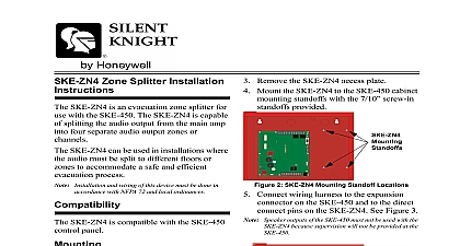
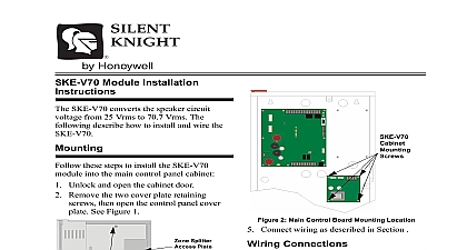
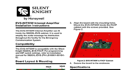
4 Mount the SKE ZN6 to the SKE 450 cabinet standoffs with the 7 10 screw in provided 2 SKE ZN6 Mounting Standoff Locations Connect wiring harness to the expansion on the SKE 450 and to the direct pins on the SKE ZN6 See Figure 3 Speaker outputs of the SKE 450 must not be used with the because supervision will not be provided at the Zone Splitter Installation SKE ZN64 is an evacuation zone splitter for with the SKE 450 The SKE ZN6 is capable splitting the audio output from the main amp six separate audio output zones or channels SKE ZN6 can be used in installations where audio must to be split to different floors or to accommodate a safe and efficient process and wiring of this device must be done in with NFPA 72 and local ordinances SKE ZN6 is compatible with the SKE 450 panel Unlock and open the SKE 450 control panel door Open the control panel cover door by the two retaining screws and the door to the left See Figure 1 Panel Retaining Access Panel Door Harness 130427 k EOL Listed 7630 3 View With SKE ZN6 Installed Wire speaker to zone outputs as required by installation specifications See the Wiring section Attach the cover plate to the SKE ZN6 See 1 SKE 450 Cabinet With Control Panel Cover In 3 Remove the SKE ZN6 access plate 151395 Zone Splitter Installation Instructions Wiring Alarm Control Wiring SKE ZN6 supplies six Notification Circuits for speaker connection The can be supervised and wired Class B Y or Class A Style Z Each circuit is of 20 watts of power The system can support a maximum of 50 watts of power Remove the cover plate on the SKE ZN6 Figure 3 To wire speakers to the control panel using B Style Y supervision see Figure 4 section describes how to connect relay from a FACP to control the four separate on the SKE ZN6 four zone splitter Connect an active low relay or contact from FACP to the Alarm Selects on the SKE See Figure 6 k EOL Listed 7630 Limited Limited k Listed EOL 7628 Limited 4 Class B Style Y Speaker Configuration To wire speaker circuits to the control panel a Class A Style Z configuration see 5 be wired 20 feet in conduit Limited 6 FACP Alarm Control Outputs Specifications Fault Impedance To Any Terminal 0 Circuit 25 Vrms or 70.7 Vrms Input Power 27.4 VDC 35 mA Input Power 27.4 VDC 120 mA 5 Class A Style Z Speaker Configuration Meridian Circle Grove MN 55369 4927 or 800 328 0103 763 493 6475 2005 Silent Knight PN 151395 Rev A