System Sensor Silent Knight IDPssb501 isheet

File Preview
Click below to download for free
Click below to download for free
File Data
| Name | system-sensor-silent-knight-idpssb501-isheet-2608319754.pdf |
|---|---|
| Type | |
| Size | 625.30 KB |
| Downloads |
Text Preview
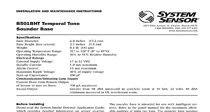
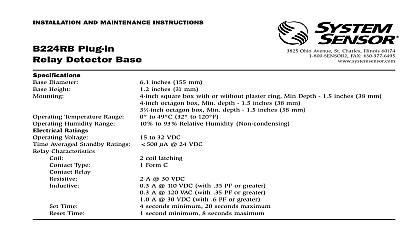
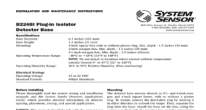
3825 Ohio Avenue Charles Illinois 60174 FAX 630 377 6495 AND MAINTENANCE INSTRUCTIONS Plug in Detector Base inches 10.2cm 60mm and 70mm centers Ratings includes base and detector Range Current nominal Surge at VDC at 24 VDC Rated Voltage Current nominal Temperature Range at 24 VDC to 150 0 to 66 Installing thoroughly read the System Sensor manual System Detectors Application Guide which provides detailed on detector spacing placement zoning wiring special applications Copies of this manual are available no charge from System Sensor Description B501 is a plug in detector base intended for use in an system with screw terminals provided for power and and remote annunciator connections The takes place over the power and Terminals Remote Annunciator Annunciator 1 Terminal layout PROOF 2 Typical wiring diagram for 2 wire loop ANNUNCIATOR Do not loop wire under terminal 1 or 2 wire run to provide supervision of connections A OPTIONAL WIRING Installation Guidelines See Figure 2 wiring must be installed in compliance with the Electrical Code and the local authority having Proper wire gauges should be used The con used to connect the smoke detectors to control and accessory devices should be color coded to pre wiring mistakes Improper connections can prevent a form responding properly in the event of a fire signal wiring the wiring between interconnected and modules it is recommended that the wiring no smaller than 18 gauge 1.0 square mm Wire sizes to 12 gauge wire 2.5 square mm may be used with the For best system performance the power and wires should be twisted pair or shielded cable in separate grounded conduit to protect the loop extraneous electrical interference If a cable shield is the shield connection to and from the base must continuous by using wire nuts crimping or soldering as for a reliable connection Connections are made by simply stripping about 3 insulation from the end of the wire use strip gauge in base sliding the bare end of the wire under the plate and tightening the clamping plate screw Do loop the wire under the clamping plate zone wiring of the detector base should be checked the detector heads are installed in them The wiring be checked for continuity polarity in the base and tests base contains a label to write the zone address and of detector to be installed at that location This infor is used to set the address of the detector head that later be plugged into the base and to verify the type for that location 3A Activating tamperproof feature 3B Removing detector head from base LEVER TAB AT LINE BY TOWARD OF BASE TO PLASTIC LEVER DIRECTION OF 4 Connection to remote annunciator terminal WIRE WITH LUG Feature Do Not use the tamper resistant capability if the or XR2B Removal Tool will be used This detector also includes an optional tamperproof feature that activated prevents removal of the detector without use of a tool activate this feature simply break off the tab on the base shown in Figure 3A and install the detector remove the detector from the base once the tamperproof has been activated place a small bladed screwdriv into the small hole on the side of the base and push the lever away from the detector head see Figure 3B will allow the detector to be rotated counterclockwise removal tamperproof feature may be defeated by breaking and the plastic lever from the base however this pre ever using the feature again Annunciator RA400 remote annunciator is connected between terminals 1 3 using the spade lug terminal packed with the remote The spade lug terminal is connected to the terminal as shown in Figure 4 is not acceptable to have three stripped wires under the wiring terminal unless they are separated by a wash or equivalent means The spade lug supplied with the RA400 is considered an equivalent means See 2 for proper installation refer to insert for the Limitations of Fire Alarm Systems Limited Warranty Sensor warrants its enclosed smoke detector base to be free from in materials and workmanship under normal use and service for a of three years from date of manufacture System Sensor makes no express warranty for this smoke detector base No agent represen dealer or employee of the Company has the authority to increase alter the obligations or limitations of this Warranty The Company of this Warranty shall be limited to the repair or replacement of part of the smoke detector base which is found to be defective in or workmanship under normal use and service during the three period commencing with the date of manufacture After phoning Sensor toll free number 800 SENSOR2 736 7672 for a Return number send defective units postage prepaid to System Repair Department RA 3825 Ohio Avenue St IL 60174 Please include a note describing the malfunction and cause of failure The Company shall not be obligated to repair or units which are found to be defective because of damage unrea use modifications or alterations occurring after the date of man In no case shall the Company be liable for any consequential or damages for breach of this or any other Warranty expressed or whatsoever even if the loss or damage is caused by the Company or fault Some states do not allow the exclusion or limitation of or consequential damages so the above limitation or exclusion not apply to you This Warranty gives you specific legal rights and may also have other rights which vary from state to state System Sensor