System Sensor WAV-CRL WAV-CWL Instruction Manual

File Preview
Click below to download for free
Click below to download for free
File Data
| Name | system-sensor-wav-crl-wav-cwl-instruction-manual-0876215943.pdf |
|---|---|
| Type | |
| Size | 3.25 MB |
| Downloads |
Text Preview
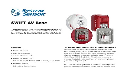
INSTALLATION AND MAINTENANCE INSTRUCTIONS WAV WL WAV CRL and WAV CWL L Series AV Base use with System Sensor L series AV devices See Table 1 for complete list Operating Voltage Range Maximum Current Draw Operating Voltage Range Maximum Standby Current Maximum Alarm Current Current Transmit RF Power Frequency Range Humidity Range Temperature Range VDC mA LED On VDC mA mA 3.3 VDC LED blink enabled dBm MHz to 93 Relative Humidity to 120 0 to 49 audio visual AV wireless base must be installed in compliance with control panel system installation manual the AV notification appliance and the SWIFT Wireless Manual The installation must meet the re of the Authority Having Jurisdiction AHJ Notificaton appliances maximum performance when installed in compliance with the National Protection Association NFPA see NFPA 72 DESCRIPTION WAV RL WAV WL WAV CRL and WAV CWL provide a wireless base use with compatible System Sensor L Series AV notification appliances in Table 1 The AV notification appliance is attached directly to the AV base See Figure 1 The wireless AV base communicates through wireless mesh to a gateway The gateway sends information to from the Fire Control Panel FACP wireless AV base provides power through 2 sets of 4 batteries one set power for the RF communication and the other set provides power to audible and or visible output on the notification appliance See Figure 2 life of the AV set of batteries depends upon the activation time of the and or visible output as indicated in Table 3 The AV base includes optional battery cartridges to ease battery replacement See Figure 2 Bat can be inserted directly into the AV base or pre loaded into the battery and inserted as two groups of 4 batteries The battery compartment cartridge indicate the correct orientation of the batteries Carefully align batteries with these markings and do not force them into place dial switches are provided on the wireless base to set the device ad See Figure 2 Notification appliance settings are adjusted through the appliance directly Temporal 3 and continuous tone patterns are and set directly on the notification appliance Refer to the specific appliance manual for available setting options offer different feature sets across the various models As a result cer features may be available on some control panels but not on others The feature sets available with Models WAV RL WAV WL WAV CRL and include An LED on the wireless base is controlled by the panel to indicate device Operational modes include red green and amber colors in vari solid or blink patterns A magnet test feature allows the individual AV appliance to be turned for testing purposes reducing the activation time needed during of the horn and or strobe in support of longer battery life refer to SWIFT Wireless Gateway Manual for complete instructions Custom and Temporal 4 patterns generated through the FACP Models WAV RL WAV WL WAV CRL and WAV CWL require compatible communications to function properly Connect these devices to Ohio Avenue St Charles Illinois 60174 FAX 630 377 6495 Type Life Replacement Wall Panasonic CR123A or 8 Duracell DL123A batteries 2 year minimum batteries See Tables 2 and 3 for AV battery life during annual maintenance or when BATTERY LOW displays 6 15 cm Width 5.1 13 cm 1.6 4 cm Ceiling Diameter 7.4 19 cm Depth 1.6 4 cm Wall Ceiling oz 499 g installed with 8 batteries oz 567 g installed with 8 batteries compatible control panels only Please refer to the operation manual for UL listed control panel for specific operation wireless AV base and notification appliance will synchronize both audio visual indications between devices located within the same mesh net Synchronization of a wireless AV device with a wired notification ap requires a synchronization module W SYNC available from System or your FACP provider Synchronization is only available through noti appliances that use the System Sensor synchronization protocol 1 AV MOUNTING ASSEMBLY WALL CEILING Wireless C2027 00 Wireless tabs Screw Sensor recommends spacing AV notification appliances in compliance NFPA 72 For specific information regarding notification appliance place and special applications refer to NFPA 72 or the Audible Visible Appli Reference Guide available from SystemSensor com technologies can exhibit communication disruption if devices are too close together To avoid this form of disruption SWIFT devices not be placed closer than 2 feet 60 cm apart without an intervening mount the wireless AV notification appliance secure the wireless AV base plate to a permanent structure An optional tamper resistance fea can be activated refer to TAMPER RESISTANCE section for details The plate can be surface mounted To avoid interference with the wire network metal electrical boxes are NOT recommended To install models and WAV CWL align the arrow on the mounting plate with the light on the AV base and rotate the AV base clockwise onto the mounting To install models WAV RL and WAV WL align the arrow on the right side the mounting base to the arrow on the side of the AV base and slide the base down onto the mounting plate See Figure 3 To attach the System L series notification appliance to the wireless AV base hook the tabs the top of the product housing into the grooves on the wireless AV base hinge the product into position to engage the pins on the product with terminals on the wireless AV base Make sure that the tabs on the back of product housing fully engage with the wireless AV base Secure the noti appliance by tightening the single mounting screw in the front of the housing See Figure 1 Attach the wireless AV base in a way that it cannot be moved after If attaching to temporary structures such as removable ceiling permanently secure the structure or mount the detector across a ceiling support 1 SYSTEM SENSOR L SERIES AV COMPATIBLE DEVICES ULC listed models have all required languages listed listed Description listed listed Description Red Wall Red Ceiling Red Ceiling Red Ceiling English Red Ceiling English Red Ceiling French Red Ceiling French White Ceiling White Ceiling English White Ceiling French White Ceiling Clear Lens Alert Canadian model Red Wall Red Wall English Red Wall French Red Wall Plain Red Wall Fuego White Wall White Wall English White Wall French White Wall Amber Lens White Wall Clear Lens White Wall Plain Strobe White Ceiling Chime Strobe White Ceiling English Chime Strobe White Ceiling French Strobe Red Wall Red Wall English Red Wall French Strobe White Wall White Wall English White Wall French White Wall Red Wall White Wall 2 wire Red Wall 2 wire Red Wall English 2 wire Red Wall French Strobe 2 wire Red Wall Plain Strobe 2 wire Red Wall Fuego Strobe 2 wire White Wall 2 wire White Wall English 2 wire White Wall French