Simplex 2001-8005 Selective Alarm Operating Instructions

File Preview
Click below to download for free
Click below to download for free
File Data
| Name | simplex-2001-8005-selective-alarm-operating-instructions-8743052691.pdf |
|---|---|
| Type | |
| Size | 1.43 MB |
| Downloads |
Text Preview
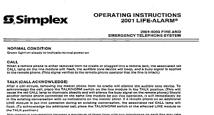
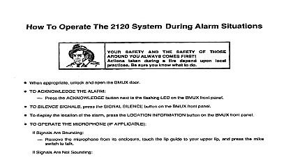
Simplex Communication Fire Alarm System Alarm 1966 Simplex Recorder Gardner Mass HAZARD electrical power when making any adjustments or repairs servicing should be performed by quali Simplex Representatives VSICE COMMUNICATION FIRE ALARM SYSTEM IS designed sound an alarm over only the speaker circuit s panel enclosed audio system circuit s in alarm The selected speaker circuit s continues sound by the specific acknowledged reset or otherwise silenced by some this audible alarm until the alarm condition at the panel locatior response to the trans of particular switches within the panel and also provides for the voicing of instructions over some all of its speaker circuits at any time including during the sounding of alarms The acknowledgement addition this system sounds alarms an alarm silences all speakers not initiated by a alarm The another source to sound feature c the system allows subsequent alarm initiation speakers if selected as well as sounding again previously selected speakers A panel which lacks an ACK button on its FIREITBL CONTROL module does not have resound capa Stopping speakers sounding by some means other than depressing ACK button i e OSC STOP switch to its position will disable the panel resound circuitry A panel which contains a TIMER module will automatically silence the signals and disable the panel circuitry after a preset duration 1 TIMER modules are required in some panels to prevent the amplifiers TIMER module has timed out by illuminating 2 The panel indicates overheating PRE AMP and MONITOR trouble lamps visible through the panel doors indicate system conditions as follows the Green NORM PWR lamps illuminated Standby Condition Power is applied to the system The system is armed and ready to respond to any alarm initiation anywhere within building or more Amber TBL lamps either flashing or steadily Trouble Condition Defects exist within The system may not be capable of responding to any or some alarm initiations One or more switches are not in the position AC power failure system internal or external circuitry ALARM lamp flashing Unacknowledged Alarm Condition At least one alarm initiating device has tripped in the zone represented by the flashing The ACK button has not been pushed to silence the speakers ALARM lamp steadily Acknowledged Alarm Condition At least one alarm initiating device has tripped in thezone The ACK button has been pushed to silence the speakers by the illuminated A panel which an ACK button on its FlRElTBL CONTROL module will cause steady illumination of an ALARM lamp during all alarm conditions ACK button on the front of the FIREITBL COIN SILENCE THE SPEAKERS DURING A SELECTIVE ALARM alarm by momentarily depressing module The speakers will resound if a fire occurs in another zone Microphone use requires manual operation the OSC STOP switch The speakers will not resound if a fire occurs The microphone will remain fully operational The panel will visually its position another zone RESET THE SYSTEM FOLLOWING SELECTIVE ALARM Locate the device s which initiated Restore the alarm initiating device s to its their standby condition Reset the panel as follows alarm trouble shortly after you transfer the OSC STOP switch Depress the RESET button on the front of the FIRE TBL CONTROL module for at least three set If the speakers were silenced by putting the OSC STOP switch the audible trouble will sound immediately upon resetting put OSC STOP switch its position and then depress the AUDIO TBL RESET push panel To silence the trouble Check to see that all SPKR CKT switches including the ALL CIRCUITS switch are in their Panels which contain a DELAY module cannot be reset until one minute after the receipt the alarm SOiJND A MANUAL ALARM Make sure all the SPKR CKT switches are in the position Select the desired alarm tone by transferring either the MANUAL ALARM AUX 1 or AUX 2 switches the position Transfer the ALL CIRCUITS switch to the position to sound the alarm over all speakers or trans sound the alarm over selected spea ker the position selected SPKR CKT switches STOP THE SOUNDING OF A MANUAL ALARM Transfer all of the switches were activated sound the manual alarm back to their USETHE MICROPHONE STANDBY CONDlTlONS Open the panel and remove the microphone Transfer the OSC STOP switch its position Transfer the ALL CIRCUITS switch to the position talk through all the speakers selected SPKR CKT switches Push the microphone button while talking Upon finishing the position talk through specific speakers Transfer activated SPKR CKT switches or the ALL CIRCUITS switch back to its po Transfer the OSC STOP switch back to its position Only necessary the system Trouble Momentarily depress AUDIO TBL RESET Place the microphone back in the panel Close and lock the panel door either an UNACKNOWLEDGED ALARM or a MANUAL ALARM Open the panel and remove the microphone Push the microphone button while talking over all unacknowledged microphone as all manually selected speaker circuits The speaker circuits activated by the unacknowledged automatic alarm or manually selected resume sounding alarm as soon as you release the microphone button the microphone button when you finish speaker circuits as an ACKNOWLEDGED ALARM Remove the microphone Transfer the OSC STOP switch to its position Transfer the ALL CIRCUITS switch to its position the panel selected SPKR CKT switches Push the microphone button while talking the microphone button when you finish the position talk through specific speakers talk through all the speakers OSC STOP Switch or after the TIMER module silences signals by activating silencing speakers Remove the microphone Push the microphone button while talking the panel microphone automatic alarm or over those speaker circuits which are selected manually over only those speaker circuits which are activated by the unacknowl the microphone button when you finish WHEN THE SYSTEM 1 Temporary which do not require service may occur during drill testing reset procedures 2 All of the following conditions An audible trouble indicator sounding when its SIUNORM switch Green NORM PWR lamp s not illuminated One or more amber lamps illuminated in the NORM position Transfer the audible Check the green NORM PWR lamps for illumination SIUNORM switch the SIL position


