Simplex 2001 Voice Communications Amplifier Monitor Module Descriptions

File Preview
Click below to download for free
Click below to download for free
File Data
| Name | simplex-2001-voice-communications-amplifier-monitor-module-descriptions-6085937124.pdf |
|---|---|
| Type | |
| Size | 1.21 MB |
| Downloads |
Text Preview
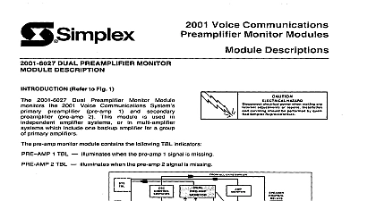
Q Simplex Modules Descriptions 1988 Simplex Time Recorder Co Gardner Mass 01441 0001 US A l 008 HAZARD electrical power when making any internal servicing be performed by qualified Simplex Representa DUAL AMPLIFIER MONITOR MODULE Fig 1 2001 6021 Dual Amplifier monitor each set of amplifiers within the system An amplifier set consists of one primary and one secondary amplifier Module used in 2001 Dual Amplifier Voice Communications Systems dual amp monitor module contains AMP TBL AMP TBL following TBL indicators when the primary amp signal is missing when the secondary amp signal is missing ALL CKTS SWITCH TBL ALARM to 2001 Voice Communications a description this block diagram Concepts REFERENCE dual amp monitor module circuitry following drawing WD No 841 052 Amplifier Monitor shown on FUNCTION Fig 2 Condition This module used systems with non trouble primary amp signal is fed to pins R and 14 of the amp monitor module and secondary amp is fed to pins 1 and 2 of the dual amp monitor When both amp signals are present relay Kl de energized and the TBL indicators are off Amplifier Monitor Module 1 Amp Trouble the primary amp signal relay Kl contacts MAIN AMP TBL indicator V sent out pin 6 System Trouble missing at pins R and 14 for more than 20 seconds Kl energizes This transfer and the following conditions occur V sent out pin M Amp Select Relay in Dual Power Amplifier Module OV sent out pin 7 to printer if used the primary amplifier signal momentarily out causing restored and the AUDIO TBL RESET switch is pressed Kl de energize This in turn causes MAIN AMP TBL indicator V on pin 12 missing at pins 1 and 2 for more than 20 seconds following conditions the secondary amp signal is again applied to pins 1 and 2 the SECONDARY AMP TBL indicator goes out Amp Trouble the secondary amp signal SECONDARY AMP TBL indicator V sent out pin 6 System Trouble V sent out pin J OV sent out pin L to printer if used POWER SUPPLY FOR PRIMARY V OV COMM PRIMARY AMP OV IN STEADY PULSING COMM SECONDARY AMP OUT TO PRINTER PRIMARY AMP TBL IN EXCEPT WHEN TBL RESET IS PRESSED V OUT WHEN PRIMARY AMP SECONDARY AMP TBL V OUT WHEN PRIMARY TBL AMP SELECT V OUT WHEN SECONDARY TBL OUT TO PRINTER SECONDARY AMP TBL TBL LED SECONDARY Amplifier Monitor Module 2 DUAL AMPLIFIER MONITOR MODULE DESCRIPTION as 2001 6021 Dual Amplifier Monitor Module except for the following This module is used in systems with resound During a primary amp or secondary amp trouble a momentary V instead of a steady V is applied to pin Drawing Reference the 6020 Dual Amplifier Monitor drawing see 2001 6020 WD No 841 255 DUAL AMPLIFIER MONITOR MODULE DESCRIPTION as 2001 6021 Dual Amplifier Monitor Module except for the following This module used in systems with resound During a primary amp or secondary amp trouble a momentary V instead of a steady V is applied to pin After a primary amp trouble an AUDIO TBL RESET is not required 6022 primary amp monitor circuitry automatically signal is applied to pins R and 14 reset the 6022 dual amp monitor module its normal condition as soon as the primary Drawing Reference the 6022 Dual Amplifier Monitor drawing see 2001 6022 WD No 841 053 DUAL AMPLIFIER MONITOR MODULE DESCRIPTION as 2001 6021 Dual Amplifier Monitor Module except for the following After a primary amp trouble an AUDIO TBL RESET is not required 6023 primary amp monitor circuitry automatically signal is applied to pins R and 14 reset the 6023 dual amp monitor module its normal condition as soon as the primary Drawing Reference the 6023 Dual Amplifier Monitor drawing see 2001 6023 WD No 841 079 SINGLE AMPLIFIER MONITOR MODULE DESCRIPTION Fig 3 2001 6025 Single Amplifier Monitor Module monitors each amplifier earlier independent amplifier systems amp monitor module contains when the amp signal is missing following TBL indicator SYS TBL ALARM PRE AMP SELECT u to 2001 Voice Communications a description this block diagram Concepts REFERENCE amp monitor module circuitry drawing WD No 841 l 56 Single Amplifier Monitor shown on the Amplifier Monitor Module 3 r FUNCTION Fig 4 Condition This module used in systems with non resound independent amp signal TBL indicator off Amp Trouble TBL indicator V sent out pin 6 System Trouble V sent out pin J OV sent out pin L to printer if used fed to pins 1 and 2 of the amp monitor module When the amp signal is present the amp signal is missing at pins 1 and 2 for more than 20 seconds following conditions occur the amp signal is again applied to pins 1 and 2 the TBL indicator goes out LED OV IN STEADY PULSING INDEPENDENT AMP POWER SUPPLY COMM V MONITOR Amplifier Monitor Module 4 OUT WHEN AMP TBL V OUT WHEN AMP TBL OV OUT TO PRINTER INDEPENDENT AMP TBL SINGLE AMPLIFIER MONITOR MODULE DESCRIPTION as 2001 6025 Single Amplifier Monitor Module except for the following This module is used in systems with resound trouble During an amplifier a momentary V instead of a steady V is applied to pin 6 Drawing Reference the 6024 Single Amplifier Monitor Module drawing see 2001 6024 WD No 841 257 Time Recorder Co Simplex Plaza Gardner Massachusetts 01441 U S A