Simplex 2081-9027 200 mA Isolated Loop Circuit Protector (ILCP) (B) (C) (D)

File Preview
Click below to download for free
Click below to download for free
File Data
| Name | simplex-2081-9027-200-ma-isolated-loop-circuit-protector-ilcp-b-c-d-8426309517.pdf |
|---|---|
| Type | |
| Size | 647.95 KB |
| Downloads |
Text Preview
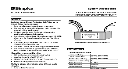
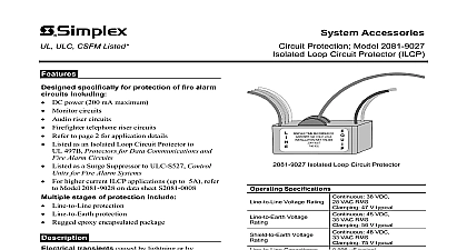
ULC CSFM Listed specifically for protection of fire alarm including DC power 200 mA maximum Monitor circuits Audio riser circuits Firefighter telephone riser circuits Refer to page 2 for application details Listed as an Isolated Loop Circuit Protector to 497B Protectors for Data Communications and Alarm Circuits Listed as a Surge Suppressor to ULC S527 Control for Fire Alarm Systems For higher current ILCP applications up to 5A refer Model 2081 9028 on data sheet S2081 0008 stages of protection include Line to Line protection Line to Earth protection Rugged epoxy encapsulated package transients caused by lightning or by on high voltage power lines are conditions that low voltage wiring circuits to be adequately This protection is most effective when placed at location where such circuits leave or enter the building Protection The 2081 9027 Isolated Loop Protector ILCP is designed to protect Simplex Alarm circuits from those electrical transients induced wire runs that are routed external to the building of its small package size it can be easily mounted the location that achieves maximum protection 1 Overvoltage Protector Applications Model is for use as an Isolated Loop Circuit Protector is different from operation as an Overvoltage For Overvoltage Protector applications refer to Protector model 2081 9044 which is listed to 864 rated for up to 200 mA and documented on data S2081 0016 2 Operation with other Circuit Types of the 2081 9028 ILCP has been quantified use with other circuit types for specific applications its low resistance is desired Contact your local product supplier for application guidance Accessories Circuit Protection Model 2081 9027 Loop Circuit Protector ILCP TIME RECORDER CO MA 01441 U S A INST 574 803 Isolated Loop Circuit Protector Specifications Voltage Rating Voltage Voltage Capacitance Current Rating Resistance 38 VDC VAC RMS 47 V typical 45 VDC VAC RMS 56 V typical 48 VDC VAC RMS 75 V typical typical mA maximum 1 Nanosecond 10 9 25 Nanosecond 10 9 2000 A 10 x 50 pulse 2000 A 8 x 20 pulse 5000 A 10 x 50 Specifications 7 W x 1 D x 1 1 H mm x 35 mm x 27 mm epoxy encapsulated 102 mm square box 54 mm minimum depth F to 120 F 0 C to 49 C RH at 30 C coded 18 AWG mm2 10 long 245 mm 14 AWG 10 long mm box requirement Rating Rating Leads Lead Instructions This product has been approved by the California State Fire Marshal CSFM pursuant to 13144.1 of the California Health and Safety Code See CSFM Listing for allowable values and or conditions concerning material presented in document This product was not FM or MEA NYC approved as of document date Additional listings may be applicable contact your local Simplex product for the latest status Listings and approvals under Simplex Time Recorder Co the property of Tyco Safety Products Westminster 4 2013 Wiring Requirements alarm system wiring that is run external to the and is protected by the use of 2081 9027 ILCPs be installed in accordance with the individual system installation instructions including properly twisted and shielded pairs and observance of following precautions To ensure optimized protection the ILCPs shall be located as close as possible to point at which the circuits leave or enter the buildings installed in dedicated metallic electrical boxes Distance Wiring is limited to one contiguous The total maximum wire length is determined the individual application allowable limit as with ILCPs but must not exceed 3270 ft 1 km Wiring Wiring must be in a wiring that is separate from commercial power wiring Application Reference Wiring Wiring must be run on poles separate from those any commercial power distribution Wiring shall be run in parallel with the commercial distribution wiring and be separated by a distance of either 100 ft 30 m or the span between any two adjacent poles of the system circuit or the commercial power circuit Conductor The grounding conductor shall be AWG 3.31 mm2 with a maximum length of 28 ft m run in as straight a line as possible and connected the building grounding electrode system unified earth per NFPA 70 the National Electrical Code Panel Type 4100U 4100 and Series Riser Telephone Riser Distance and Notes ft 1 km maximum 4010ES 4100U 4020 and 4120 Series Points and MAPNET II Monitor Zone Connections 2 Wire Detectors 50 maximum Dry Contacts 800 maximum 3270 ft 1 km maximum whichever is shorter ft 610 m maximum or 10 maximum whichever is Typical Connection Reference refer to Installation Instructions 574 803 for additional information square box 2 1 8 deep 54 mm separately Equipment ILCP Refer to to where to shield A B AWG min circuit ground screw A B the next Ground connections for the protected and the Overvoltage Protector must part of the same Grounding Electrode System Ground connection 12 AWG 28 ft 8.5 m maximum SIMPLEX and the product names listed in this material are marks and or registered marks Unauthorized use is strictly prohibited NFPA and the National Electrical Code trademarks of the National Fire Protection Association 2013 Tyco Fire Protection Products All rights reserved All specifications and other information shown were current as of document revision date and are subject to change without notice Fire Protection Products Westminster MA 01441 0001 USA 4 2013