Simplex 2081-9044 Overvoltage Protector Installation Instructions

File Preview
Click below to download for free
Click below to download for free
File Data
| Name | simplex-2081-9044-overvoltage-protector-installation-instructions-8342516907.pdf |
|---|---|
| Type | |
| Size | 607.46 KB |
| Downloads |
Text Preview
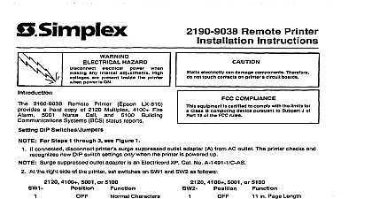
Model 2081 9044 Protector Instructions Simplex Model 2081 9044 protects Simplex building system equipment from overvoltage conditions induced on runs that are external to the building 2081 9044 is listed as compatible with the following circuits 4120 Network Communications RS 485 only DC power to ZAMs and Annunciators MAPNET II Communications RUI Communications 2120 Communications City Circuit Wiring Local energy only operating voltage 27VAC RMS line to line 35VAC RMS line to ground operating current MA resistance Ohms per line 6 Ohms per protector PROCEDURE See illustration on next page For optimum protection install the 2081 9044 apart from the protected equipment and as close as practical to the where the circuit leaves or enters the building Protected and unprotected wiring must not share the same conduit Mount the protector in a 4 in 10.16 cm or larger square box At least 2 in 5.08 cm distance must separate the from the conduit Cut the protector green lead as short as possible and tie it to the mounting box with a standard grounding II Communication Net is protected by U S Patent No 4,796,025 1995 2000 Simplex Time Recorder Co Westminster MA 01441 0001 U S A specifications and other information shown were current as of publication and are subject to change without notice 574 832 5 95 Bond the box containing the protector to the grounding electrode system of the building containing the protected Use 12 AWG 3.309 mm2 or larger solid copper wire The ground wire length must not exceed 28 ft 8.6 m Bends in the ground wire of less than 2 in 5.08 cm radius are not permitted If enclosed in metal conduit the ground wire must be bonded to the conduit at both ends A Connect the protector brown and violet leads to the lines coming from the protected equipment Connect the protector orange and yellow leads to the lines going out of the building Connect one of the protector gray leads to one of the cable shields Then connect the remaining gray lead the other shield separate the two cables At the protector dress the input and output cables as far apart as possible no less than 2 in 5.08 cm distance At the signal source connect the cable shield to the cabinet ground screw The following represent signal sources BMUX for 2120 Communications or fire alarm panel for all other circuits CONNECTIONS STEP ABOVE IN SQUARE BOX MIN A B SHIELD SCREW AWG MIN AWG MIN FT MAX A B THE ORANGE YELLOW LEADS ANOTHER 2081 9044 574 832 5 95 2081 9044 Protector Instructions Simplex Model 2081 9044 protects Simplex building system equipment from overvoltage conditions induced on runs that are external to the building 2081 9044 is listed as compatible with the following circuits 4120 Network Communications RS 485 only DC power to ZAMs and Annunciators MAPNET II Communications RUI Communications 2120 Communications City Circuit Wiring Local energy only operating voltage 27VAC RMS line to line 35VAC RMS line to ground operating current MA resistance Ohms per line 6 Ohms per protector PROCEDURE See illustration on next page For optimum protection install the 2081 9044 apart from the protected equipment and as close as practical to the where the circuit leaves or enters the building Protected and unprotected wiring must not share the same conduit Mount the protector in a 4 in 10.16 cm or larger square box At least 2 in 5.08 cm distance must separate the from the conduit Cut the protector green lead as short as possible and tie it to the mounting box with a standard grounding II Communication Net is protected by U S Patent No 4,796,025 1995 2000 Simplex Time Recorder Co Westminster MA 01441 0001 U S A specifications and other information shown were current as of publication and are subject to change without notice 574 832 5 95 Bond the box containing the protector to the grounding electrode system of the building containing the protected Use 12 AWG 3.309 mm2 or larger solid copper wire The ground wire length must not exceed 28 ft 8.6 m Bends in the ground wire of less than 2 in 5.08 cm radius are not permitted If enclosed in metal conduit the ground wire must be bonded to the conduit at both ends A Connect the protector brown and violet leads to the lines coming from the protected equipment Connect the protector orange and yellow leads to the lines going out of the building Connect one of the protector gray leads to one of the cable shields Then connect the remaining gray lead the other shield separate the two cables At the protector dress the input and output cables as far apart as possible no less than 2 in 5.08 cm distance At the signal source connect the cable shield to the cabinet ground screw The following represent signal sources BMUX for 2120 Communications or fire alarm panel for all other circuits CONNECTIONS STEP ABOVE IN SQUARE BOX MIN A B SHIELD SCREW AWG MIN AWG MIN FT MAX A B THE ORANGE YELLOW LEADS ANOTHER 2081 9044 574 832 5 95