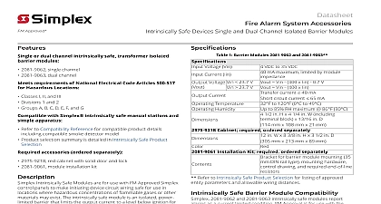
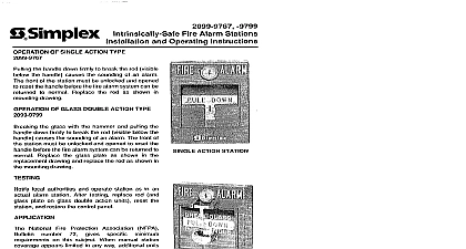
Simplex 2081-9062 9063 Intrinsically Safe Single & Dual Isolated Barrier Modules (B)(C)(D)

File Preview
Click below to download for free
Click below to download for free
File Data
| Name | simplex-2081-9062-9063-intrinsically-safe-single-dual-isolated-barrier-modules-b-c-d-4652893170.pdf |
|---|---|
| Type | |
| Size | 731.51 KB |
| Downloads |
Text Preview
FM Approved or dual channel intrinsically safe isolated barrier modules 2081 9062 Single channel 2081 9063 Dual channel requirements of National Electrical Code 500 517 for Hazardous Locations Classes I II III Divisions 1 2 Groups A B C D E F G with Simplex intrinsically safe stations and simple apparatus Refer to page 2 for compatible product details compatible smoke detector model Product selection summary is detailed on page 7 accessories ordered separately 2975 9218 Red cabinet with solid door and lock 2081 9061 Module installation kit Intrinsically Safe Modules are for use with FM Simplex control panels to make initiating circuit wiring safe for use in locations where concentrations of flammable gases or other may exist The intrinsically safe module is an power limited barrier that limits the output to a level below ignition for atmospheres defined NEC Articles 500 517 for Classes I II III 1 2 Groups A B C D E F G Considerations The installation of safe modules requires strict adherence to compatibility lists and must be in accordance with product installation instructions and applicable codes wiring practices all applicable references thoroughly before the intrinsically safe design Alarm System Accessories Intrinsically Safe Devices and Dual Channel Isolated Barrier Modules by Safe Barrier Module Mounted in Cabinet with cover removed wiring and conduit shown for reference only Modules 2081 9062 and 2081 9063 Voltage Vin to 35 VDC Current Iin mA maximum limited by module 23.7 V VOUT VIN 400 x IIN 0.7 V 23.7 V VOUT VIN 400 x IIN Current Temperature Humidity current cid 100 40 mA circuit current cid 100 65 mA F to 120 cid 113 F 0 cid 113 C to 49 cid 113 C to 85 RH maximum 86 F 30 C Cabinet Required Ordered Separately H x 4 1 4 W including terminal x 13 16 D 114 mm x 108 mm x mm W x 8 3 8 H x 3 1 2 D mm x 213 mm x 89 mm for barrier module mounting mm DIN rail type mounting control drawing and end of line resistors Installation Kit Required Ordered Separately 10 2003 Refer to page 2 for listing exceptions This application is FM approved only Contact your Simplex product supplier for additional information Listings and approvals under Time Recorder Co are the property of Tyco Safety Products Westminster Refer to page 7 for listing of approved entity parameters and allowable wiring distances NOTE Intrinsically Safe applications are NOT with Alarm Verification Intrinsically Safe Barrier Module Compatibility 2081 9062 and 2081 9063 Intrinsically Safe report alarms as a current limited condition FM is for use with the Simplex fire alarm control and peripheral devices described in the following chart Compatibility Reference Simplex Fire Alarm Control Panels and Modules Series and 4005 Class B IDCs both standard and current B IDCs B IDC module 4100 5004 B IDC module 4100 5005 Adapter Modules ZAMs B surface cover MAPNET II communications only B flush cover MAPNET II communications only Initiating Devices Stations Series Action Station Action Breakglass Station Apparatus B for use with compatible Simplex fire alarm control panels MAPNET II or IDNet device which does not store or generate more than 1.2 V 100 mA or 20 cid 80 J typically a dry contact heat detector or switch Smoke Detector NOTE NOT FM APPROVED but tested as compatible with IDCs listed IDCs Intrinsically Safe Photoelectric Smoke Detector Model SLR E IS with Hochiki Intrinsically Safe Base Model YBN R 4 IS NOTE Five 5 maximum per circuit Available from Hochiki Although the above listed peripheral model numbers are FM Approved as Intrinsically Safe except as noted peripheral devices and any simple apparatus must be selected for proper fire protection compatibility the dust content and corrosion potential of the atmosphere to be protected Installation Requirements All equipment MUST be installed in accordance with National Electrical Code NEC ANSI NFPA 70 504 and ANSI ISA RP 12.6 1987 Cable and or conduit from Non Hazardous and locations MUST enter the barrier enclosure opposite sides and MUST be sealed per National Code Article 504 Safe circuits MUST NOT be installed in same cable conduit or raceway with safe circuits Safe circuits are for indoor applications Maximum line resistance from the Fire Alarm panel to last device in the Hazardous location is 10 cid 58 The 2975 9218 cabinet must be equipped with a safety per NEC Article 250 42 The grounding must be 12 AWG 3.31 mm2 minimum the is not grounded For additional wiring information reference the Electrical Code Articles 500 through 517 and Control Drawing 842 070 Refer to page 7 for approved entity parameter reference 10 2003 Installation Reference alarm input block green bracket output terminal blue by to grounding conductor AWG minimum module and or conduit between and hazardous area be sealed per National Code Article 504 Wiring Diagram Reference below is for reference only refer to Control Diagram 842 070 for complete installation details Location Simplex B Initiating Device Single Module In 11 In 12 Out 1 Out 2 4090 9101 ZAM k cid 58 cid 15 cid 3 1 2 W 378 054 is here In 11 In 12 Out 1 Out 2 In 9 In 10 Out 4 Out 5 Dual Module required per NFPA 70 504 70 Location I II III DIV 1 2 A B C D E F G Resistor Stations or 2099 9799 other devices that qualify simple apparatus Intrinsically safe circuits are for indoor applications only k cid 58 4002 k cid 58 for 4100 UT k cid 58 10 2003 Electrical Code Hazardous Location Classifications I Locations III Division 1 I locations are those in which flammable gases or are or may be present in the air in quantities to produce explosive or ignitable mixtures Class III Division 1 location is a location in which ignitable fibers or materials producing combustible are handled manufactured or used I Division 1 Class I Division 1 location is a location Note Division 2 Categories marked Division 1 is suitable for both 1 and Division 2 locations which ignitable concentrations of flammable gases vapors can exist under normal operating or Definitions I which ignitable concentrations of such gases or may exist frequently because of repair or operations or because of leakage or which breakdown or faulty operation of equipment processes might release ignitable concentrations of gases or vapors and might also cause failure of electric equipment II Locations II locations are those that are hazardous because of presence of combustible dust II Division 1 Class II Division 1 location is a location which combustibl


