Simplex 2098-9110 Ionization Detector

File Preview
Click below to download for free
Click below to download for free
File Data
| Name | simplex-2098-9110-ionization-detector-1870654329.pdf |
|---|---|
| Type | |
| Size | 596.90 KB |
| Downloads |
Text Preview
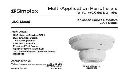
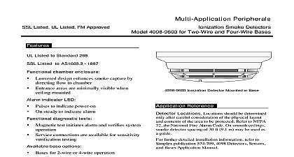
Simplex Peripherals Accessories Listed Smoke Detectors Series ULC Listed to Standard S529 Dual Chamber Design Two Wire Operation LED Alarm Indicator Functional Test Feature Optional Remote Alarm LED 360 Smoke Entry for Optimum Smoke Range 15 to 32 VDC VDC nominal Current 100 max Current 47 mA 24 VDC Range 32 F to 100 F C to 38 C Range 10 to 93 RH Velocity Limits 300 ft min max than 1.0 Microcurie AM 241 Off White 2098 9110 Smoke Detector has two chambers an sampling chamber and an inner reference cham Smoke or invisible combustion gasses can freely the outer chamber but the inner chamber is closed to smoke entry With both chambers ion by a single radioactive source Am 241 a very current flows in the circuit The combustion parti present act as recombination centres which resistance across the chamber resulting in a re current flow The reduced current flow is by the detector and when it falls below a pre level an alarm is transmitted to the fire alarm panel Detector Alarm Indicator 2000 Simplex Int Time Equipment Co Ltd 6 00 detector is supplied with a mounting trim ring that the detector to be used with several mounting Units may be mounted directly to a 3 1 2 or 4 1 1 2 deep No 125 or equivalent box Units may be mounted to a 4 square electrical box using a plaster ring not included with the trim ring Units may be mounted directly to the ceiling or wall the plastic screw anchors packed with the ring For direct mounting the trim ring is used a template and 3 16 holes are drilled for the anchors For this application reference local smoke detectors are to be connected only to compatible Simplex control equipment detectors should not be installed near outlets supply air ducts Avoid the use of smoke detectors there is an inherent high risk factor of instanta combustion such as in kitchens boiler rooms rooms or areas where welding or soldering done locations should be determined only after consideration is made of the physical layout and of the protected area Refer to ULC Standard for guidelines On smooth ceilings spacing of 30 9.1m may be used as a guide SWITCH SLOT MODULE Refer to wiring diagrams provided with system for proper panel connections 841 687 Refer to wiring diagrams provided with system for proper end of line resistor value Typically control unit two wire detection circuits will load down appreciably upon activation of one or more alarm indicating devices can prevent operation of other devices connected to the same alarm initiating circuit Maximum quantity of detectors per initiating circuit is 18 6 00 Skymark Avenue Mississauga Ontario L4W 5K5 and Representatives Throughout the World us on the World Wide Web www simplexnet com specifications and other information shown were current as of printing and are subject to change without notice Printed in Canada