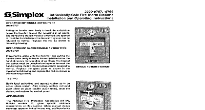
Simplex 2099 Series Non-Coded Fire Alarm Stations Installation and Operating Instructions

File Preview
Click below to download for free
Click below to download for free
File Data
| Name | simplex-2099-series-non-coded-fire-alarm-stations-installation-and-operating-instructions-1746295083.pdf |
|---|---|
| Type | |
| Size | 1.23 MB |
| Downloads |
Text Preview
2099 Series Non Coded Fire Alarm Stations and Operating Instructions On all 2099 Stations installed unlocking and the front of the station an alarm DOWN Action Station 1 GLASS PULL DOWN Action Station Glass 3 Action Station with Cover 2 DOWN Action Station Type 4 Alarm Station Operation Action Stations 2099 9101 9102 9754 9755 Figure 1 the handle down firmly to break the rod visible below the handle the sounding of an alarm and the actuation of annunciator contacts provided The front of the station must be unlocked and opened to reset handle before the fire alarm system can be returned to normal Replace rod as shown in mounting drawing see Figure 7 Action Station with Pre signal Alarm 2099 9107 Figure 1 the handle down firmly to break the rod visible below the handle the sounding of a pre signal alarm actuates the annunciator contacts provided and exposes the general alarm key switch Insert and turn the key to sound a general alarm The front of the station must be and opened to reset the handle before the fire alarm system can be to normal Replace the rod as shown in mounting drawing see 7 Action Station with Institutional Cover 2099 9762 Figure 2 and opening the station causes the sounding of a general alarm station must be closed and locked before the fire alarm system can be to normal Action Stations Break Glass 2099 9103 9104 9105 Figure 3 the glass with the hammer and pulling the handle down firmly to the rod visible below the handle causes the sounding of an alarm the actuation of annunciator contacts if provided The front of the must be unlocked and opened to reset the handle before the fire system can be returned to normal Replace the glass plate as shown the replacement drawing see Figure 5 and replace the rod as shown in mounting drawing see Figure 7 Action Station with Pre signal Alarm Break Glass 2099 9108 Figure 3 the glass with the hammer and pulling the handle down firmly to the rod visible below the handle causes the sounding of a pre signal actuates the annunciator contacts if provided and exposes the alarm key switch Insert and turn the proper key to sound a general The front of the station must be unlocked and opened to reset the before the fire alarm system can be returned to normal Replace the plate see Figure 5 as shown in the replacement drawing and replace rod as shown in the mounting drawing see Figure 7 Action Station Push Type 2099 9756 9757 9758 Figure 4 on the push bar and then pulling the handle down firmly to break rod visible below the handle causes the sounding of an alarm and the of annunciator contacts if provided The front of the station be unlocked and opened to reset the handle before the fire alarm can be returned to normal Replace the rod as shown in mounting see Figure 7 Action Station with Pre signal Alarm Push Type 2099 9759 4 on the push bar and then pulling the handle down firmly to break rod visible below the handle causes the sounding of a pre signal actuates the annunciator contacts if provided and exposes the alarm key switch Insert and turn the proper key to sound a general The front of the station must be unlocked and opened to reset the before the fire alarm system can be returned to normal Replace the as shown in mounting drawing see Figure 7 2000 Simplex Time Recorder Co Westminster MA 01441 0001 USA specifications and other information shown were current as of publication and are subject to change without notice A local authorities and operate station as in an actual alarm station After testing replace rod and glass plate on glass double action units reset station and restore the control panel of Glass on Double Action Break Glass Type Figure 5 View View 5 Double Action Station Glass Plate Replacement Swing Hammer A away from front of pull station Fit glass retainer B onto bottom of glass plate C Then top of glass plate behind tab Slide glass retainer B into station until it snaps into place Gently return hammer A to its normal position National Fire Protection Association NFPA Bulletin 72 gives specific minimum requirements on this When manual station coverage appears limited in any additional units should be installed Stations should be with the bottom of the station not less than 3 1 2 ft or more than 5 feet 1.52M from the floor Usually are mounted at the 4 1 2 ft 1.4M level order to make building and facilities accessible to and by the physically handicapped some specifications may that the station be installed not more than 3 1 2 ft from the floor should be located in the normal path of exit and in the protected area so that they are unobstructed readily accessible should be provided on each floor to obtain a travel of not more than 200 feet 60.96M to the nearest from any point in the building One station should be for each floor where the maximum floor area is 10,000 feet 929 sq meters or more One station should be on the first floor and on each succeeding alternate if the areas to be protected are smaller than the limits as above semi flush mounting Figures 6 and 8 use a standard 10.16cm square outlet box with a minimum depth of 2 1 8 fitted with a 3 4 1.9cm deep single gang switch set flush DO NOT RECESS or protruding 1 16 16cm the wall surface 2099 9103 9754 9755 9756 or 9762 be semi flush mounted by using a standard single gang box 3 x 2 7.62cm x 5.08cm with a minimum depth of 3.65cm with conduit KO set flush DO NOT or protruding 1 16 16cm from the wall surface surface mounting Figures 7 and 8 use a 2975 9178 red back box or a 2975 9022 aluminum back box Do not a box with a depth less than 2 3 16 5.55cm The 2099 9103 9754 9755 9756 or 9762 can surface mounted by using a wiremold box no formerly A 3 6 Semi Flush Station Mounting 7 Surface Station Mounting 8 Alternate Semi Flush and Surface Station Mounting No 18 AWG minimum No 14 AWG maximum Terminal Specification For System supervision do not use looped wire under terminals Break wire run to provide supervision of connections Type Connections Version Units Normally open contact closed on Alarm Normally closed contact open on Alarm Cover marking Institutional cover marking Operated only and Contact Arrangements ID ALARM A


