Simplex 2120 Multiplex Interface Installation Manual

File Preview
Click below to download for free
Click below to download for free
File Data
| Name | simplex-2120-multiplex-interface-installation-manual-0836215947.pdf |
|---|---|
| Type | |
| Size | 902.39 KB |
| Downloads |
Text Preview
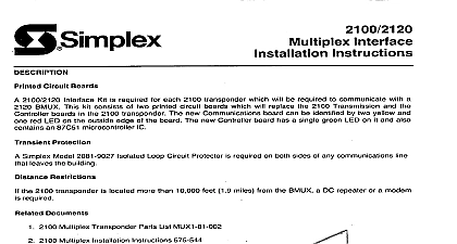
a Simplex Circuit Boards Kit is required communicate with a 2100 2120 the BMUX This kit consists of two printed circuit boards which will replace boards can be identified by two yellow and red LED on the outside edge of the board The new Controller board has a single green LED on it and also an 87C51 microcontroller which will be required new Communications 2100 Transmission each 2100 the 2100 Loop Circuit Protector required on both sides of any communications located more than 10,000 1.9 miles from the BMUX a DC repeater or a modem Protection Simplex Model 2081 9027 leaves the building Restrktions the 2100 required Documents 2100 Multiplex Transponder Parts List MUX1 81 002 2100 Multiplex 575 544 AC power and batteries all board DC and each 2100 transponder See Figure 1 for board locations 2100 CPU and to the replacement 2120 Model 2098 2097 on any DC communication the building Circuit that called for Install any repeaters or modems on communication Be sure that the polarity of the communication A and A are correct and the B and B lines are negative McCulloh connections are A and B terminals are the 1999SimplexTime Manuals Online Co Gardner Mass 01441 0001 U S A BD BD BD BD BOARDS BE REPLACED 1 Transponder the Anti static Kit Part No 553 503 when handling boards 7 no alterations need to be made to the board operated style 7 contact Board Preparation not operated Support at Headquarters McCulloh Board banks of dip switches on operate These switch banks are read and stored by the microcontroller are RESET button must be pressed or the power must be removed and re applied transponder the settings changed controller board which must be configured powered the new settings pressed the power up or when the RESET be read and Card Address Switch Settings and SW2 switches on switch banks SW1 and SW2 are numbered 0 to 15 and are set ON if their number corresponds the transponder These addresses are found by either a looking them up an encoder card address present the 2100 TRANSPONDER SPECIFICATION SHEETS for the particular being converted or by b reading jumpers on the mother board of the transponder These four jumpers are located next to the encoder card a bit in a four bit address and is either a binary one by connected address simply up the binary weights 12 Volts or a binary zero by being connected Figure 2 Each jumper corresponds each bit tied to 12 Volts GND To determine to Figure 2 jumpers on the second encoder card are con as follows encoder binary slot address would address 4 28 NOC encoder card has an address of 2 8 10 determined along the encoder card address edge appropriate dip switch ON These switches are split into the board switch banks The the button and is labeled EC numbers 0 to 7 for numbers 0 thru 7 The second bank EC 8 to 15 for encoder numbers 8 thru 15 the side of the board and bank next transponder procedure to ten every encoder card a dip switch set for an encoder card does not exist an error will be Likewise a dip switch is not set error will be reported encoder QQQQ is NC is NO is NO is NC Make no ENCODERS ADDRESS USE EACH POINT MUST HAVE A JUMPER MUST HAVE A JUMPER 2 Transponder Mother Bd Manuals Online Rate baud rate is set by setting dip switches 1 and 2 of switch bank SW3 These two dip switches are labeled Figure 3 Use the following to set these switches to the proper baud rate A AAAAA SWITCHES FOR SWITCHES Setting 3 Bd 3 through 8 of switch bank SW3 are for setting the transponder address Each dip switch carries a binary corresponding its position These switches are labeled and the switches with a binary weight 1 and 32 are marked The address of the transponder the example shown Figure 3 is 18 second 2100 transponder manner which other 2120 transponder addresses are set Remember less than the transponder number the control point transponder The first address occupies transponder second Set the ADDR dip switches next consecutive address This is done the address of the the always transponder the monitor point Power down the 2100 transponder disconnecting both battery and AC power Prepare the 2100 Transponder the 2100 2120 boards as described above transmitting the communication labeled PRI and SEC and indicate activity on the primary and secondary channels of the transponder A and B terminals on the 2100 are the primary terminals the slot which the 2100 Transmission board previously occupied two yellow LED s will flicker indicating of DC transmissions The LED s the the controller board in the slot previously occupied by the 2100 Controller board Manuals Online Apply first AC power and then battery power to the transponder while observing green LINE LED 10 seconds Replace controller board if either The LED fails to flash at a high rate about 10 flashes second power up The LED continues at a high rate 10 or more seconds after power on The 8 second watch dog timer test which takes place while the green LED flashes at a high rate can be by pressing RESET button Check the green LINE LED again it is not on steady to the TROUBLE DIAGNOSIS chart below the green ON LINE LED remains secure the transponder Installation replace complete cover over the PC boards on the transponder Close message Symptoms EC XPNDR