Simplex 2190-9039 Remote Printer Installation Instructions
File Preview
Click below to download for free
Click below to download for free
File Data
| Name | simplex-2190-9039-remote-printer-installation-instructions-2398467105.pdf |
|---|---|
| Type | |
| Size | 4.70 MB |
| Downloads |
Text Preview
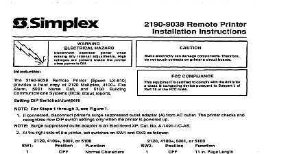
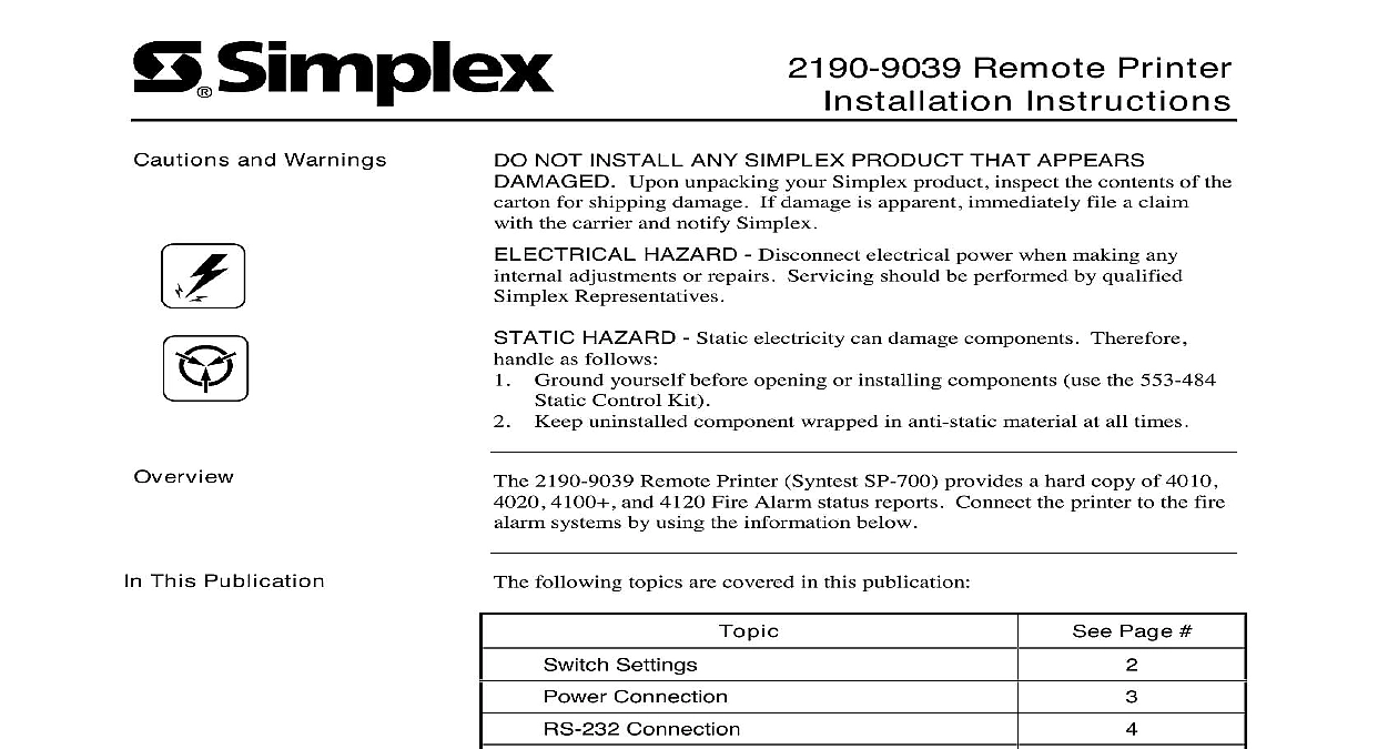
Cautions and Warnings Remote Printer Instructions NOT INSTALL ANY SIMPLEX PRODUCT THAT APPEARS Upon unpacking your Simplex product inspect the contents of the for shipping damage If damage is apparent immediately file a claim the carrier and notify Simplex HAZARD Disconnect electrical power when making any adjustments or repairs Servicing should be performed by qualified Representatives HAZARD Static electricity can damage components Therefore as follows Ground yourself before opening or installing components use the 553 484 Control Kit Keep uninstalled component wrapped in anti static material at all times 2190 9039 Remote Printer Syntest SP 700 provides a hard copy of 4010 4100 and 4120 Fire Alarm status reports Connect the printer to the fire systems by using the information below This Publication following topics are covered in this publication Page Settings Connection Connection Front Panel Programming for an Printer Port Information 2000 Simplex Time Recorder Co Westminster MA 01441 0001 USA specifications and other information shown were current as of publication and are subject to change without notice B Settings Settings switches SW1 and SW2 according to Figure 1 Access the switches by two plastic plugs on the printer bottom cover Rate Bits Default Panel Values Shown 1 Switch Settings Connection Connection to wiring diagram 841 731 for interconnection wiring information 24 VDC printer power is supplied from either the Master Power Board or the Expansion Power Module located within the 4100 Fire Alarm Power is channeled to the printer via a two wire adapter plug supplied printer inserted into a five pin DIN connector Figure 2 The two wires are connected to system 24 V power using cable with the requirements Use 14 AWG wire if distance is less than 395 ft Use 12 AWG wire if distance is greater than 395 ft but less than 625 ft Black Wire to 0 V Pin 5 VDC Red Wire to 24 VDC Pin 4 2 Power Connector Connection Connection RS 232 harness to either Port 1 via TB1 or P3 or Port 2 via TB2 or as indicated in Figure 3 Wiring pin numbering is shown in wiring diagram Observe harness tag for proper harness number 3 RS 232 Terminal Connections on next page Connection Continued Connection to Figure 4 below to wire the 2190 9039 Remote Printer to the RS 232 of a 4100 Panel 5 7 the proper harness is to the printer and Card 4 Wiring the Printer to a 4100 RS 232 Card to Figures 5 and 6 below to wire the 2190 9039 Remote Printer to a 4010 4020 Fire Alarm Control Panel the proper harness is connected to the printer and Card to the Front Panel Programming for an Printer Port section of this document if you are the printer to a 4010 FACP or 8 or 9 or 10 RS232 CARD USED PRINTER PRINTER 5 Wiring the Printer to a 4010 RS 232 Card 6 Wiring the Printer to a 4020 RS 232 Card Front Panel Programming for an RS 232 Port an RS 232 Card section describes programming a printer port on a 4010 RS 232 card from front panel of the 4010 FACP Login to the system at access level 4 before attempting to the port section describes adding the RS 232 card to the 4010 job Press MENU Press NEXT or PREVIOUS until PROGRAMMING is displayed then press ENTER The following warning appears indicating that 4010 is no longer in the Fire Alarm Operation mode Wait Alarm Operation Suspended Press ENTER to continue Press NEXT or PREVIOUS until CONFIGURE CARDS is and then press ENTER Press NEXT or PREVIOUS until ADD A 4010 CARD is and then press ENTER Press NEXT or PREVIOUS until RS232 is displayed and then ENTER Press ENTER again to confirm that you want to add RS 232 card A message appears indicating that the system is the card the EXIT key once to move back one menu level and then continue with Step 5 in the next section the following steps to configure the printer settings baud rate etc for the port to which the printer is attached Before beginning ensure you the hardware settings enabled on the printer i e baud rate set on printer Press MENU Press NEXT or PREVIOUS until PROGRAMMING is displayed then press ENTER A warning appears indicating that the 4010 is longer in the Fire Alarm Operation mode Wait Alarm Operation Suspended Press ENTER to continue on next page RS 232 Port Front Panel Programming for an RS 232 Port Continued RS 232 Port continued Press NEXT or PREVIOUS until CONFIGURE CARDS is and then press ENTER Press NEXT or PREVIOUS until MODIFY 4010 CARD is and then press ENTER Press NEXT or PREVIOUS until the display reads TYPE RS232 CARD and then press ENTER Press NEXT or PREVIOUS to select either PORT A or B and then press ENTER display similar to the following appears allowing you to set the settings for the port to ACCEPT ARROW KEYS to Change BAUD 9600 Parity None Use the arrow keys to move the bracket to the PORT Parameter Use the and PREVIOUS keys to select a choice for this parameter that you must have an 80 column printer to print 4010 reports are as follows PRT80U Unsupervised 80 column printer Unused PRT40S Supervised 40 column printer PRT40U Unsupervised 40 column printer PRT80S Supervised 80 column printer Use the arrow keys to move the bracket to the BAUD Parameter Use the and PREVIOUS keys to select a choice for this parameter are as follows Use the arrow keys to move the bracket to the PARITY parameter Use NEXT and PREVIOUS keys to select a choice for this parameter are as follows None Even Odd Press ENTER A display similar to the following appears allowing you select which events are routed to the printer ENTER to Send ALL Events to Port NEXT to Select Events on next page Front Panel Programming for an RS 232 Port Continued RS 232 Port continued Choose which events are sent to the printer when they occur as follows All Events to Printer Press ENTER to send all of the events in Table 1 below to the printer After you press ENTER the indicates that the option is updated and exits to the MODIFY 4010 selection in the Programming menu Press the EXIT key twice message appears indicating that the configuration has changed Move to SAVE CFIG choice and press ENTER Another message appears you to confirm the Save operation Press ENTER to save the new Specific Events to Printer Press NEXT to individually select events are sent to the printer when they occur A series of prompts of which is listed in Table 1 appears For each prompt press the and PREVIOUS keys to toggle between the YES and NO When the setting is correct press ENTER After the last appears the system promp