Simplex 4001-9403 and -9404 Fire Alarm Systems General Information

File Preview
Click below to download for free
Click below to download for free
File Data
| Name | simplex-4001-9403-and-9404-fire-alarm-systems-general-information-8297403516.pdf |
|---|---|
| Type | |
| Size | 732.93 KB |
| Downloads |
Text Preview
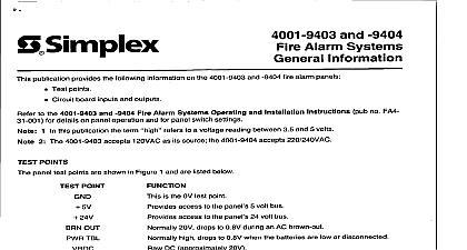
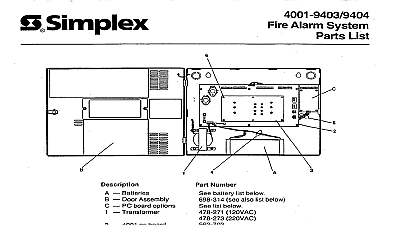
a and 9404 Alarm Systems publication provides following on the 4001 9403 and 9404 fire alarm panels Test points Circuit board inputs and outputs details on panel operation and for panel switch settings to the 4001 9403 and 9404 Fire Alarm Systems Operating and Installation 1 In this publication 2 The 4001 9403 accepts 120VAC as its source the 4001 9404 accepts 220 240VAC to a voltage reading between 3.5 and 5 volts term no FA4 POINTS panel test points are shown in Figure 1 and are listed below is the OV test point access to the panel 5 volt bus access to the panel 24 volt bus 2OV drops to 0.8V during an AC brown out high drops to 0.8V when the batteries are low or disconnected DC approximately 28V high drops to 0.8V when there is an open on the city lines read voltage between desired test point and the GND test point POINT 24V OUT TBL TBL 24V DlJT TBL Test Points 1 1986 Simplex Recorder Gardner Mass o M 000 INPUTS AND OUTPUTS are five terminal blocks that are used to interface external devices to the panel block TBl interfaces panel power supply to the transformer and batteries secondary secondary terminal terminal block TB2 interfaces if used panel to the signal circuits 4 wire detectors if used and remote acknowledge input activated on the remote annunciator the terminal of an external power source Can be up to the remote acknowledge an open circuit floating when switch 2.3 mA 2A maximum are being used are being used or the OV line of an external power source output is 32V average at up to 2 amps the wire of the 4 wire detector power the wire of the 4 wire detector power the wire of the signal circuit the wire of the signal circuit Under normal non alarm voltage output is 24VDC at 1.8 mA Under alarm conditions if 4 wire if 4 wire block TB3 interfaces a trouble relay panel to an annunciator and remote trouble station Terminals are also provided contact of trouble relay of trouble relay contact of trouble relay 1 2 3 4 remote trouble remote line provides 24VDC block TB4 interfaces panel to the initiating device circuits zones 1 line 24VDC 1 line 2 line 24VDC 2 line 3 line 24VDC 3 line 4 line 24VDC 4 line contacts of relay 1 of relay 1 contacts of relay 1 contacts of relay 2 of relay 2 contacts of relay 2 block TB5 interfaces panel to the city loop and also provides access to auxiliary relay contacts city line 24VDC city line 24VDC 2 88 l 001