Simplex 4005 Series 4005 Fire Alarm Control Panels (D)

File Preview
Click below to download for free
Click below to download for free
File Data
| Name | simplex-4005-series-4005-fire-alarm-control-panels-d-4630857291.pdf |
|---|---|
| Type | |
| Size | 743.15 KB |
| Downloads |
Text Preview
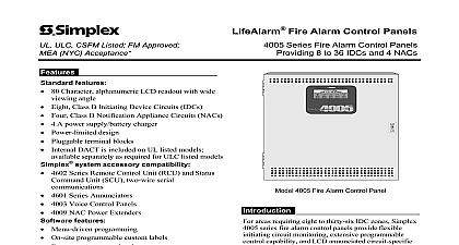
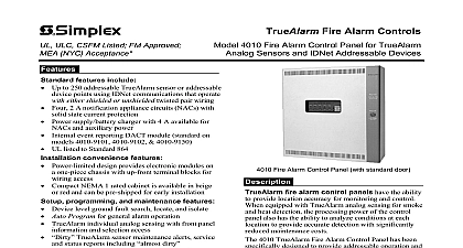
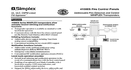
ULC CSFM Listed FM Approved NYC Acceptance Fire Alarm Control Panels 4005 Series Fire Alarm Control Panels 8 to 36 IDCs and 4 NACs features 80 Character alphanumeric LCD readout with wide angle Eight Class B Initiating Device Circuits IDCs Four Class B Notification Appliance Circuits NACs 4 A power supply battery charger Power limited design Pluggable terminal blocks Internal DACT is included on UL listed models separately as required for ULC listed models system accessory compatibility 4602 Series Remote Control Unit RCU and Status AND C POWER Unit SCU two wire serial 4601 Series Annunciators 4003 Voice Control Panels 4009 NAC Power Extenders features Menu driven programming On site programmable custom labels Four operator access levels Historical event logs Circuit selectable alarm verification WALKTEST one person system testing Selectable active status reminder expansion Two circuit IDC two circuit NAC relay Four circuit NAC relay Four circuit IDC low current and high current Four circuit Class A NAC or IDC zone conversion Eight circuit I O module Remote station city connection Additional 5 A power supply Listed to Standard 864 Refer to page 6 for additional ULC listing information This product has been approved by California State Fire Marshal CSFM pursuant to Section 13144.1 of the California and Safety Code See CSFM Listing 7165 0026 212 for allowable values and or concerning material presented in this document It is subject to revision and possible cancellation Accepted for use City of New York of Buildings MEA35 93E See page 7 for ULC designations Additional may be applicable contact your local Simplex product supplier for the latest Listings and approvals under Simplex Time Recorder Co are the property of Tyco Products Westminster 4005 Fire Alarm Control Panel areas requiring eight to thirty six IDC zones Simplex series fire alarm control panels provide flexible circuit monitoring extensive programmable capability and LCD annunciated circuit specific labels Surface mount components efficient programming and easy to use control operation combine to provide an extensive feature in a compact friendly package status and circuit information is efficiently by an alphanumeric LCD readout featuring two of 40 characters each The panel control switches are marked for intuitive operation Programming of selectable features is performed by using the display the panel control switches while in the programming 4005 series fire alarm control panel provides for a wide variety of mid size facilities in the fields Educational Health Care Business Hospitality Residential and General Assembly modular design allows IDCs and NACs to be in groups of two or four to satisfy circuit without specifying excess capacity If the expands then additional modules be easily installed on site WALKTEST performance testing is protected under US Patent No 4,725,818 NACs may be individually configured for dry contact relay operation Contact your local Simplex product supplier for fire alarm control panels suitable for Control applications 3 2009 4005 Module Features CPU board contains the main microprocessor and programming evaluates the status of all I O processes the required responses and provides a timer that resets the panel in the event of an operation Additional details are below Controls the LCD readout and switches that comprise operator interface Controls the flash EPROM that contains the non volatile programming information 4 Wire Smoke Detector Power provides a 5 second rated 500 mA 24 VDC open collector output is power limited and short circuit protected Remote Unit Serial Interface RUI output provides for up to 16 Class B supervised remote Remote Control Unit RCU model Status Command Unit SCU model see additional description under on page 5 Distribution Board Features Provides connections for up to 5 plug in module cards Auxiliary power connections Two power limited are provided each rated for 2 A 24 VDC are isolated from NAC power Supply Battery Charger features Switch Selectable for 120 or 240 VAC 24 VDC Power regulated and power limited is specifically for notification appliances and output use via two taps of 2 A each rated 4 A Special Application Appliances and 2 A for 24 DC power System Operating Power is supplied via power limited connections Battery Charging for up to 18 Ah batteries mounted the 4005 cabinet and up to 33 Ah batteries when in an external battery cabinet Function Monitoring Includes missing depleted and battery Earth fault detection AC power loss AC brownout low input voltage signal power supply voltage monitoring and charger failure Depleted Battery Trouble Indication advises when operation has exceeded battery capacity DACT Module features Reports Alarm Supervisory Trouble and AC Failure Dual line operation with automatic 24 hour test and power fail report delay Initiating Device Circuits IDCs features Two 4 circuit IDC plug in modules are standard 8 Class B IDCs Standard IDCs are low current and support up to 20 detectors per IDC at 2 mA maximum for with relay bases use high current expansion see chart on page 7 4005 Module Features Continued operation is individually programmable with following 28 operating mode choices the abbreviated is part of the IDC display information Detector Detector Detector Pump Fire Type Description Monitor WaterFlow Open Closed Open Closed Point Type Description FPUMP SFPUMP S2STAGE 2 Stage Monitor SO SC WSO Pull Detector WSC SUPV UTIL Monitor TROUBLE Trouble Monitor VSMOKE Verified Smoke GVMON Verified Generator LATSUPV Supervisory STYLEC Monitor Style C Supervisory Appliance Circuits NACs 4 circuit NAC Relay plug in module is standard 4 Class B NACs that can be individually for dry contact relay operation operation is individually programmable as Signaling Temporal Pattern March Time BPM or March Time 120 BPM and with the 17 operating modes the abbreviated is part of the NAC display information Type Description Signal On Silence Signal On Reset On Clear On ACK On until On until Signal Circuit WaterFlow On Silence Point Type Description RWATER WaterFlow On Reset PRIMARY Elevator Capture ALTERN Capture AHUR AHUO AHUF DHOLDER Door Holder Off Relay On Relay Relay 3 2009 NAC Relay Mode Operation Selection Each NAC can be on sit


