Simplex 4006-9801 Expansion Power Supply Rev A

File Preview
Click below to download for free
Click below to download for free
File Data
| Name | simplex-4006-9801-expansion-power-supply-rev-a-0647935812.pdf |
|---|---|
| Type | |
| Size | 741.02 KB |
| Downloads |
Text Preview
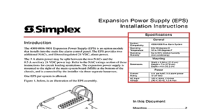
Expansion Power Supply EPS Installation Instructions 4008 4006 9801 Expansion Power Supply EPS is an option module installs into the main fire alarm control panel The EPS provides two NACs and filtered regulated 24 VDC alarm power 3 A alarm power may be split between the two NACs and the A auxiliary 24 VDC power tap Refer to the NAC ratings section of these for circuit loading restrictions The expansion power supply is to the right of the main system board MSB at the bottom of the and is connected by the installer via three separate harnesses EPS per system is allowed 1 below is an illustration of the EPS assembly Input Fire Alarm System to 49 degrees C to 120 degrees F to 93 relative humidity condensing 4.38 in 11.2 cm 7 in 17.8 cm 4 in 10.2 cm A per NAC 3 A alarm power 24 VDC V 60Hz 2 A max V 50 Hz 1.5 A max this Document interconnections 3 wiring 5 24 V wiring 6 ratings 7 Figure 1 The Expansion Power Supply EPS assembly is shipped with the following EPS assembly bracket with two PCBs Screws washers 441 002 qty 2 AC harness 734 179 black white leads Battery harness 734 180 red black leads Data flex harness 166 438 flat cable This document contains instructions on installing the EPS into the fire control panel For programming instructions refer to the Front Panel Operating and Programming Instructions 579 704 for 4006 or for 4008 2004 Tyco Safety Products Westminster MA 01441 USA All specifications were current and are subject to change without notice 579 707 A Manuals Online http Power Supply EPS Installation Instructions the EPS to the main annunciation cabinet as shown the figure below the EPS to the cabinet with slotted torx screws 441 002 Figure 2 Mounting the EPS Manuals Online http Power Supply EPS Installation Instructions interconnections the following steps and the figure on the next page to the EPS to the Main System Board MSB Remove AC and battery power from the panel You be wiring to the AC line Be sure the circuit is OFF and tagged You have the option of removing the Depleted Battery jumper R76 on the EPS Removing the has the following effects system will NOT initiate an alarm if the first occurs after the depleted battery state has detected system will shut down 60 seconds after the battery condition is detected the jumper if required Note that there is a option in the programmer that must be see the Front Panel Installing Operating and Instructions 579 704 for 4006 for 4008 Connect the data flex harness 166 438 from J1 on EPS to on the 4006 9801 on the 4008 9801 The AC harness 734 179 is used to connect AC from the MSB to the EPS source is 120 VAC 60 Hz single phase or VAC nominal 50 Hz single phase 3 8 insulation from the black and white the black wire lead to the LEFT MSB power terminal TB4 marked the white wire lead to the RIGHT MSB power terminal TB4 marked the snap on AC harness connector to P6 the EPS Connect the battery harness 734 180 from P3 on the to the battery connector on the MSB P13 on the P14 on the 4008 Do not connect the harness to batteries until you are ready to power up the Connectors should be aligned such that P13 or P14 on the MSB the red wire is on the and the black wire is on the right P3 on the EPS the red wire is on the bottom the black wire is on top closer to R76 see figure on the next page Manuals Online http Power Supply EPS Installation Instructions SYSTEM BOARD BATTERY JUMPER on 4008 on 4006 POWER AC AND BATTERY AND FROM BREAKER WIRING THE POWER DATA FLEX BOARD on 4008 on 4006 on 4008 on 4006 HARNESS LEFT ON P13 P14 BOTTOM P3 RIGHT ON P13 P14 ON P3 BATTERY JUMPER BOARD AREA PORTION OF BOARD OBSCURED TOP OF ASSEMBLY HARNESS LEFT ON TB4 RIGHT ON P6 RIGHT ON TB4 LEFT ON P6 Figure 3 Interconnections between the MSB and EPS Manuals Online http Power Supply EPS Installation Instructions NAC wiring CABINET NAC upwards B WIRING NAC wiring from the EPS is routed within the as shown above NAC terminals accept 18 AWG to 12 AWG Larger wire reduces line loss and longer wiring distance from the FACP the notification appliances Use a VOM to test conductors for grounds stray voltages before connection to and panel All wiring is supervised and Power Limited Circuits must not be Terminate each Class B circuit with a k 0.5 W resistor 733 894 For Canadian mount the end of line resistor TEPG US Model 431537 EOL Plate per Wire Class A Style Z NACs from and to each appliance No end of line is for Class A Connect wires from on the last appliance to and A the EPS The 10 k 0.5 W brown black orange factory installed should remain across and on unused to keep them in the normal state Current rating Each NAC supplies 2 A application EPS provides 3 A is split between AUX 24 V and NAC Refer to the NAC ratings section of instructions for circuit loading Terminal designations are for the alarm state If wiring is routed outside the building use of a listed secondary is required Use 2081 9028 or 2081 9044 A protector be installed at each building exit entrance Each2081 9028 0.2 Ohms wiring resistance 2081 9044 adds 6 Ohms The wiring chart to the right gives the maximum distance for 0.25 to 2 A loads Class B distance panel terminals to the last appliance Class A distance EPS terminals to the last appliance and to the EPS terminals When using non addressable Series 4901 4903 and 4904 two audible visible appliances maximum wiring capacitance is uF Determine wiring capacitance by adding wire to wire plus wire to shield capacitance if shield is used the result by the wire length in feet Example A 12 AWG is rated at 100 pF foot with no shield The 0.22 uF limit a maximum length of 2,200 ft Also check the wiring chart right to determine that the voltage drop will not excessive Max number of Smart Sync appliances 2 A divided by the draw amperage of the appliances used AUDIBLE VISIBLE APPLIANCES ON POWER SUPPLY B B A A A A NAC4 A WIRING AUDIBLE VISIBLE APPLIANCES ON POWER SUPPLY B A A B A A NAC4 Distance from Panel to Last Device Feet AWG AWG AWG AWG allows for a drop of 3.4 V due to wire resistance Wire resistance given is for wire at 50 C 122 F Figure 4 NAC Wiring Class A and B Manuals Online http Power Supply EPS Installa