Simplex 4009 IDNet NAC Extender System Board Installation Instructions

File Preview
Click below to download for free
Click below to download for free
File Data
| Name | simplex-4009-idnet-nac-extender-system-board-installation-instructions-7305491862.pdf |
|---|---|
| Type | |
| Size | 952.20 KB |
| Downloads |
Text Preview
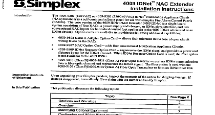
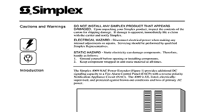
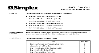
4009 IDNet NAC Extender Board Instructions and Warnings NOT INSTALL ANY SIMPLEX PRODUCT THAT APPEARS DAMAGED Upon unpacking your Simplex product inspect the of the carton for shipping damage If damage is apparent immediately file a claim with the carrier and notify Simplex Hazard Disconnect electrical power when making any internal adjustments or repairs Servicing should be performed by Simplex Representatives HAZARD Static electricity can damage components Therefore handle as follows Ground yourself before opening or installing components use the 553 484 Static Control Kit Keep uninstalled component wrapped in anti static material at all times FREQUENCY ENERGY This equipment generates uses and can radiate radio frequency energy and if not installed and used accordance with the instruction manual may cause interference to radio communications It has been tested and found to comply with limits for a Class A computing device pursuant to Subpart J of Part 15 of FCC Rules which are designed to provide reasonable against such interference when operated in a commercial environment Operation of this equipment in a residential area is likely cause interference in which case the user at his own expense will be required to take whatever measures may be required to correct the publication shows how to install the System Board Part No 565 771 into a 4009 IDNet NAC Extender 4009 IDNet to the 4009 IDNet NAC Installation Instructions 574 181 for configuration information the 4009 IDNet NAC Extender Field Diagram 842 068 for additional wiring information and the 4009 IDNet NAC Basic Configuration Wiring and Trouble Shooting 526496 located on the inside of the 4009 IDNet door assembly Board Configuration 4009 IDNet configuration is set by System Board DIP Switch SW1 Hardware and SW2 Software The replacement 4009 IDNet board DIP switch s SW1 and SW2 must be set identical to the configuration its replacing Make a note of current settings on the system board to be replaced and refer to the 4009 IDNet NAC Installation Instructions 574 181 and the 4009 IDNet NAC Basic Wiring and Trouble Shooting Procedures 526 496 located on the inside of the 4009 IDNet door assembly Notes for removing the System Board to Figure 1 and the 4009 IDNet NAC Extender Field Wiring Diagram 842 068 Using a Key unlock and open the door assembly on the 4009 IDNet Disconnect the 4009 IDNet Batteries Remove AC Power from the 4009 IDNet at the breaker Field Wiring may remain attached to the option cards Mark and remove all field wiring internal wiring and option cards connected to the 4009 IDNet system board Remove four torx screws securing the system board to the mounting plate Using gentle pressure remove the system board from the snap ins that hold the board in place Notes for installing the System Board to Figure 1 and the 4009 IDNet NAC Extender Field Wiring Diagram 842 068 Attach the system board to the snaps ins and secure the board to the mounting plate using four torx screws Connect AC Power Connect the 4009 IDNet Batteries Test the 4009 IDNet for proper Alarm and Trouble operation and configuration before locking the all removed field wiring internal wiring and option cards and connect them to the replacement system board assembly 1999 Simplex Time Recorder Co Gardner MA 01441 0001 USA specifications and other information shown were current as of publication and are subject to change without notice is a trademark of Simplex Time Recorder Company B IDNet Cards Note 4 Screws 4 3 Field Wiring Interface TB4 Note 2 Cutout P5 Version 2 Power TB5 Notes 5 Control Field Interface Note 2 A Card A Card Addressable NAC System Board YEL H2 BLK NAC Card Repeater Card or Receiver Card Charger Inputs Wire P8 Wire P9 Note 5 Input TB7 Note 5 Rectifier Inputs Wire to Positive Terminal of Bridge Wire H2 to Negative Terminal of Bridge Note 5 Refer to the 4009 IDNet NAC Extender Field Wiring Diagram 842 068 for additional wiring information 4009 IDNet provides NAC Control via the IDNet Interface TB4 or the Hardwired Control Interface TB5 only one of these two interfaces will field wiring connected to its terminals detailed information on the Hardware Configuration Switch SW1 and Software Configuration Switch SW2 refer to the 4009 IDNet NAC Installation 574 181 and the 4009 IDNet NAC Basic Configuration Wiring and Trouble Shooting Procedures 526 496 located on the inside of the 4009 door assembly necessary refer to the following installation instructions for the 4009 IDNet option Cards Optic Link Installation Instructions 574 182 Option Card Installation Instructions 574 325 A Adapter Installation Instructions 574 326 Repeater Card Installation Instructions 574 327 Maintain correct polarity on these connections 1 4009 IDNet System Board Connections IDNet Cards Note 4 B