Simplex 4010 SFIO Programmed IC Installation Instructions

File Preview
Click below to download for free
Click below to download for free
File Data
| Name | simplex-4010-sfio-programmed-ic-installation-instructions-0431926785.pdf |
|---|---|
| Type | |
| Size | 774.05 KB |
| Downloads |
Text Preview
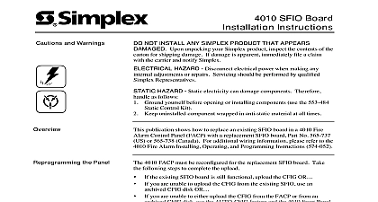
Cautions and Warnings SFIO Programmed IC Instructions NOT INSTALL ANY SIMPLEX PRODUCT THAT APPEARS Upon unpacking your Simplex product inspect the contents of the for shipping damage If damage is apparent immediately file a claim the carrier and notify Simplex HAZARD Disconnect electrical power when making any adjustments or repairs Servicing should be performed by qualified Representatives HAZARD Static electricity can damage components Therefore as follows Ground yourself before opening or installing components use the 553 484 Control Kit Keep uninstalled component wrapped in anti static material at all times publication shows how to replace an existing 742 147 IC U25 in a 4010 Alarm Control Panel FACP with a replacement programmed IC For wiring information refer to the 4010 Fire Alarm Installing Operating Programming Instructions 574 052 During this procedure the FACP is not a functional fire Inform building personnel and the local fire as required steps must take place to complete the IC replacement Check off Steps 1 3 as you complete each task 1 or upload the existing program CFIG from the FACP to PC the existing IC and install the replacement IC 2 3 Download the Rev 2.01 or higher master EXEC File 4010 BIN the archived programming information from your PC to the When upgrading the firmware to version 2.01 of the programmed IC the PC Programmer must at Rev 2.01 or higher Using a Key unlock and open the door assembly on the FACP Remove the retainer from the panel Disconnect the FACP batteries Remove AC Power from the FACP at the breaker Check Aux 1 and Aux 2 terminals for any external from field wiring Remove the voltage at the before attempting to replace IC U25 the SFIO Chip remove the programmed IC U25 from an SFIO board in an FACP follow 1 through 8 and refer to Figures 1 and 2 1999 Simplex Time Recorder Co Gardner MA 01441 0001 USA specifications and other information shown were current as of publication and are subject to change without notice A the SFIO Chip Using a T 15 Torx driver unscrew the four No 6 screws that connect the mounting plate assembly from the SFIO mounting plate Gently lift the keyboard mounting assembly straight outward Disconnect keypad harness connecting the keyboard mounting assembly to the SFIO P11 Set the keyboard mounting plate assembly aside Pay careful attention to avoid pulling at the keypad that connects the keyboard mounting assembly the SFIO Board P11 If the harness is damaged the likely symptom is a CRASH 0A all LEDs flash the piezo constantly sounds Locate the IC U25 on the SFIO board The IC is positioned half way the right side of the board next to P7 see Figure 2 With an IC Extractor 553 412 553 413 or compatible tool remove the IC the SFIO board Box Board Assembly 1 Expanded View of a 4010 FACP the SFIO Chip install the replacement IC into an FACP follow Steps 1 through 7 and refer Figure 2 The top left corner of the IC is flat as shown Figure 2 The flat edge of the IC must be aligned the flat edge of the socket for proper installation The replacement IC can be installed by hand or by using an IC Inserter the replacement SFIO chip properly orientated gently snap it into Align the keyboard mounting assembly over the SFIO board assembly the harness to the SFIO and reconnect the keypad harness to the connector s Attach the keyboard mounting assembly to the SFIO mounting plate assembly Pay careful attention to the 3 pin connector on the right of the display which plugs into P7 on the SFI O This connector can be damaged if pressure is applied during installation PTCs in the lower left corner of the SFIO must not touch each other or any other metal surface Use caution when PTCs the edges are sharp Check the baud rate settings by referring to the 4010 Fire Alarm Installing and Programming Instructions 574 052 Reapply power to the FACP Connect the AC power first and then connect SFIO Board Edge SFIO IC U25 in panel power Verify that all FACP operations work properly Re install the retainer into the panel Port 2 Expanded View of SFIO IC U25 FACP must be reconfigured for the replacement IC If after completing the you experience problems refer to the following information a negative Earth ground is detected that was not present prior to chip replacement check the Switching Regulator U51 U51 is on the bottom left corner of the board This regulator touches the display thus creating a ground you are unable to download the CFIG from the PC use an archived CFIG OR you are unable to either download the CFIG from the PC or from an CFIG disk use the AUTO CFIG feature from the 4010 Front Panel PC Programmer to restore the original CFIG data base functionality from copy records A