Simplex 4090-9117 4090-9117 Addressable Power Isolator for 4100ES, 4100U and 4010ES Series Fire Alarm Controls
File Preview
Click below to download for free
Click below to download for free
File Data
| Name | simplex-4090-9117-4090-9117-addressable-power-isolator-for-4100es-4100u-and-4010es-series-fire-alarm-controls-7643829015.pdf |
|---|---|
| Type | |
| Size | 986.97 KB |
| Downloads |
Text Preview
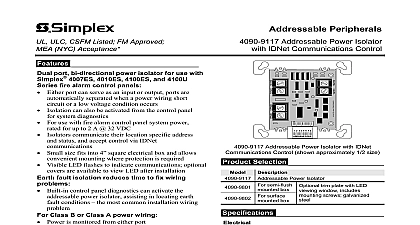
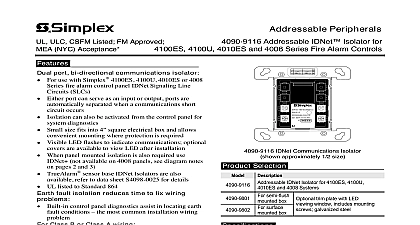
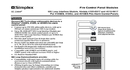
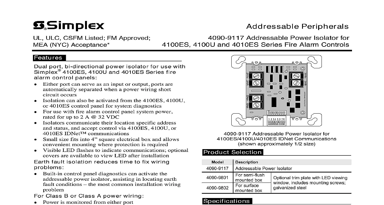
ULC CSFM Listed FM Approved NYC Acceptance Peripherals 4090 9117 Addressable Power Isolator for 4100U and 4010ES Series Fire Alarm Controls port bi directional power isolator for use with 4100ES 4100U and 4010ES Series fire control panels Either port can serve as an input or output ports are separated when a power wiring short occurs can also be activated from the 4100ES 4100U 4010ES control panel for system diagnostics For use with fire alarm control panel system power for up to 2 A 32 VDC communicate their location specific address status and accept control via 4100ES 4100U or IDNet communications Small size fits into 4 square electrical box and allows mounting where protection is required Visible LED flashes to indicate communications optional are available to view LED after installation fault isolation reduces time to fix wiring Built in control panel diagnostics can activate the power isolator assisting in locating earth conditions the most common installation wiring Class B or Class A power wiring Power is monitored from either port Two Isolators can be connected to produce Class A wiring that can optimize operation by connection with devices outside of the wiring section listed to Standard 864 Circuit Isolation Under normal conditions the Addressable Power Isolator provides continuity ports In the event of a short circuit or if requested the control panel the isolator opens a two pole switch isolating both power circuit conductors Isolators power up in isolation mode and are to connect by the control panel If the output is acceptable the isolator will connect to the rest the circuit If the output wiring is shorted the isolator isolated Tracking The isolator reports to the panel when it in isolation mode and the extent of shorted wiring is at the panel by identifying non communicating addresses Isolators are assigned sequentially to low addresses to expedite Signaling Line Circuit SLC Refer to Installation Instructions 574 873 for information Faults During system installation earth faults occur Finding these faults normally requires wiring disconnection With the Addressable Isolator earth faults on fire alarm system power can be more quickly located to expedite repair Addressable Power Isolator for IDNet Communications approximately 1 2 size Addressable Power Isolator Selection semi flush box surface box trim plate with LED viewing includes mounting screws steel Rating A maximum 32 VDC maximum Power mA maximum 24 VDC system power IDNet 1 address one load terminals for input and output wiring to 14 AWG 0.82 mm2 to 2.08 mm2 two up to 12 AWG 3.31 mm2 one to individual devices for wiring distances with 2081 9028 Circuit Protector to 2500 ft 762 m from fire alarm control to 10,000 ft 3048 m total wiring distance T Taps with Simplex 2081 9044 Protectors Connections Reference Wiring Reference H x 4 1 8 W x 1 3 8 D mm x 105 mm x 35 mm to 120 F 0 to 49 C indoor operation only Range This product has been approved by the California State Fire Marshal CSFM pursuant to to 90 RH at 90 F 32 C 13144.1 of the California Health and Safety Code See CSFM Listing for allowable values and or conditions concerning material presented in document It is subject to re examination revision and possible cancellation listings may be applicable contact your local Simplex product supplier for the status PWR ISOLATORON1 2 3 4 5 6 7 8ADDRESS CODE1 2 3 4 5 6 7 8firealarmresources com Power Isolator Multi Floor Example 1 Circuit Isolation The one line diagram on this shows a multiple floor example with Class B IDNet and conventional Class B power wiring floor wiring starts at an isolator If any floor beyond the isolator experiences a short circuit floor will be individually separated from the next the short circuit from disabling the entire run Fault Isolation In the event of an earth wiring each floor power wiring can be individually using 4100ES 4100U 4010ES control panel This narrows the search area by the isolated wiring section and can result in the time required to locate and correct the fault sensor housing relay output handling syste m in which it is installed variab les such as dilution aatification over which this device is attached as a secondary detection device NOT REMO VE THI S NOTICE 2 3 4 5 6 7 8 24V 0V IDNET IDNET ZONE PWR PWR IDC TI ME R ECORDER CO MONITOR Z AM CLASS B INSTR 574 183 COD E 1 Adapter floor local floor floor PWR I SO LAT OR 1 2 3 4 5 6 7 8 2 3 4 5 6 7 8 C ODE PWR I SO LAT OR 1 2 3 4 5 6 7 8 2 3 4 5 6 7 8 C ODE PWR I SO LAT OR 1 2 3 4 5 6 7 8 2 3 4 5 6 7 8 C ODE power VDC nominal duct sensor relay output wire see wiring notes B risers PWR I SO LAT OR 1 2 3 4 5 6 7 8 2 3 4 5 6 7 8 C ODE 9117 IDNet Power Isolator sensor with relay base Addressable Isolator 9116 see note 3 Notes This is a one line drawing showing only IDNet communications and power wiring Operation of the 4090 9117 Addressable IDNet Power Isolator requires connection to a 4100ES 4100U or 4010ES IDNet communications channel IDNet isolators are shown for typical reference but are not required 4100 ES Series Control Panel for reference Power Isolator Multi Floor Example 2 A Wiring The illustration below is a modification Example 1 Each floor wiring loop connects to the next in a Class A connection From the last device the returns to the panel providing a secondary path is monitored for loop integrity Class A power wiring available from a 4100ES 4100U 4010ES Fire Control programmed for this application using two 4090 Power Isolators mounted close nippled at the panel Assistance It is recommended that for A wiring isolators be located as the first and last in the loop as shown below With the resulting isolation flexibility locating earth wiring faults be made easier Remote Device IDNet Device see note 3 Wiring Example A riser with Class B using Isolators sensor housing relay output handling syste m in which it is installed variab les such as over which this device is attached as a secondary detection device NOT REMO VE THI S NOTICE floor local 2 3 4 5 6 7 8 24V 0V IDNET IDNET ZONE PWR PWR IDC TI ME R ECORDER CO MONITOR Z AM CLASS B INSTR 574 183 COD E 1 floor Adapter 1 2 3 4 5 6 7 8 2 3 4 5 6 7 8 C ODE 1 2 3 4 5 6 7 8 2 3 4 5 6 7 8 C ODE ON 1 2 3 4 5 6 7 8 2 3 4 5 6 7 8 C ODE 24VB 24VA IDNet ON ADDRESS C ODE 2 3 4 5 6