Simplex 4090-9118 Relay IAM (Individual Addressable Module) with T-Sense for use with 4100ES, 4100U, or 4010ES IDNet Communications

File Preview
Click below to download for free
Click below to download for free
File Data
| Name | simplex-4090-9118-relay-iam-individual-addressable-module-with-t-sense-for-use-with-4100es-4100u-or-4010es-idnet-communications-5806249317.pdf |
|---|---|
| Type | |
| Size | 648.17 KB |
| Downloads |
Text Preview
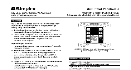
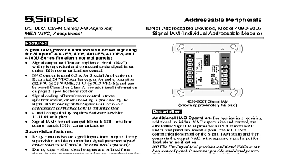
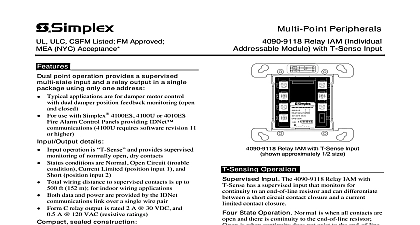
ULC CSFM Listed FM Approved NYC Acceptance Peripherals 4090 9118 Relay IAM Individual Module with T Sense Input point operation provides a supervised input and a relay output in a single using only one address Typical applications are for damper motor control with damper position feedback monitoring open and For use with Simplex 4007ES 4010ES 4100ES or Fire Alarm Control Panels providing IDNet 4100U requires software revision 11 higher details operation is and provides supervised of normally open dry contacts Status conditions are Normal Open Circuit trouble Current Limited position input 1 and Short input 2 Total wiring distance to supervised contacts is up to ft 152 m for indoor wiring applications Low power latching relay design allows IDNet to supply both data and module power Relay is set to OFF on initial power up and upon loss of communications Form C relay output is rated 2 A 30 VDC and A 120 VAC resistive ratings sealed construction Enclosed design minimizes dust infiltration Mounts in standard 4 square electrical box Visible LED flashes to indicate communications Screw terminals for wiring connections Optional covers are available to allow LED to be after installation Listed to Standard 864 Address Dual Point Module The 4090 9118 IAM with T Sense allows a compatible Simplex fire control panel IDNet communication channel to two input contact closures with one point and an output relay with the other point both from a module requiring a single address Module power supplied from the IDNet communications channel the need for separate power wiring Device Description The input circuit and operation are controlled independently and may be separately Point association is determined at the panel At the host panel display the device address is as a single hardware location such as 1 1 individual points are considered and are underneath such as 1 1 1 and 1 1 2 Relay IAM with T Sense Input approximately 1 2 size Operation Input The 4090 9118 Relay IAM with has a supervised input that monitors for to an end of line resistor and can differentiate a short circuit contact closure and a current contact closure State Operation Normal is when all contacts are and there is continuity to the end of line resistor is when continuity does not exist to the end of line causing a Trouble condition Short indicates that contact has closed that is directly connected to the input and Current Limited indicates that a contact has beyond a series connected current limiting resistor operation allows differentiation between two contact types due to their wiring location and as a single IDNet addressable point to the fire control panel Applications Package For smoke control applications this provides an efficient package for fan damper with position feedback The monitor point can be to two separate status indicator switches the host panel to track the fan damper status with to the requested fan control operation Applications The monitor and control points be applied for a variety of associated or independent Flexible programming abilities at the host can provide the association logic required for a variety of fire or utility operations This product has been approved by the California State Fire Marshal CSFM pursuant to 13144.1 of the California Health and Safety Code See CSFM Listing 7300 0026 311 allowable values and or conditions concerning material presented in this document for use City of New York Department of Buildings MEA35 93E Additional may be applicable contact your local Simplex product supplier for the latest status and approvals under Simplex Time Recorder Co are the property of Tyco Fire Products 11 2014 Product Selection IAM with T Sense Adapter and Trim Plates plate to fit 4 11 119 mm square electrical box semi flush mounted box surface mounted box Resistor Harnesses ordered separately as required Plate galvanized steel with LED viewing window includes mounting for current limited monitoring refer to diagram below No Description k 1 2 W k 1 2 W T Sense Input Operating Modes Circuit Status Modes Position Monitoring Status Modes Status circuit Status Limited Status Limited Status open discontinuity Status A closed B closed Status switch closed switch closed and Tamper Switch Monitoring Status Modes Wiring Reference distance to contacts is 500 ft m input is for indoor wiring only k 1 2 W Input limited k W communications host control panel next device Wiring Distances Up to 2500 ft 762 m from host control panel Up to 10,000 ft 3048 m total wiring distance including T taps Display Panel Display Closed Open Display Alarm IAM T Sense Fire Alarm applications locate within 3 ft 1 m of contacts Limited Contact Ratings A 30 VDC resistive loads A 30 VDC inductive loads Limited Contact A 120 VAC resistive loads A 120 VAC inductive loads to specifications for additional Refer to Installation Instructions 574 874 for detailed installation information 11 2014 Mounting Information setting under label 102 mm square box 2 1 8 mm minimum depth RACO or equal supplied by others Relay IAM T Sense gang blank cover plate and mounting screws for when LED is not required to be externally viewed by others Reference Double Gang Blank Cover Plate mm mm pipe for LED viewing 116 mm Trim plate for mounted box 109 mm Trim plate for mounted box Trim Plates for Visible LED 11 2014 Specifications Allocation Requirements Supervision Resistors Connections communications one address one unit load power supplied from a compatible IDNet channel Type TRIAM Point Usage per Panel 2 1 for relay 1 for input Points Usage up to 3 1 for relay 1 for input 1 for trouble for points mapped to the Fire Alarm open dry contacts to 500 ft 152 m total distance from Relay IAM indoor wiring applications only required refer to Installation Instructions 574 874 for additional information wiring detail terminals for input and output wiring 18 to 14 AWG wire mm2 to 2.08 mm2 A 30 VDC resistive A 30 VDC inductive A 120 VAC resistive A 120 VAC inductive listed fire alarm supply Contact Ratings C SPDT rated for switching Provide circuit fusing and transient suppression as required per application DC inductive loads can typically be diode suppressed VAC loads may require RC networks or varistors depending on device type Refer to Installation Instructions 574 874 for information Wiring Distance Reference Range Instructions to 2500 ft 762 m from the fire alarm control panel to 10,000 ft 3048 m total Class B wiring distance including T Taps with 2081 9044 Overvoltage Protectors H x 4 1 8 W x 1 3 8 D 105 mm x 105 mm x 35 mm thermoplastic hou