Simplex 4090-9120 4090-9120 Six Point Module with Four T-Sense Inputs and Two Relay Outputs

File Preview
Click below to download for free
Click below to download for free
File Data
| Name | simplex-4090-9120-4090-9120-six-point-module-with-four-t-sense-inputs-and-two-relay-outputs-3908456712.pdf |
|---|---|
| Type | |
| Size | 819.59 KB |
| Downloads |
Text Preview
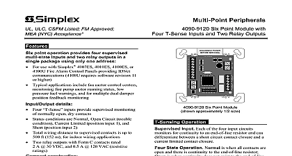
ULC CSFM Listed FM Approved NYC Acceptance Peripherals 4090 9120 Six Point Module with T Sense Inputs and Two Relay Outputs point operation provides four supervised inputs and two relay outputs in a package using only one address For use with Simplex 4100ES 4100U or 4010ES Alarm Control Panels providing IDNet 4100U requires software revision 11 higher Typical applications include fan motor control centers fire pump motor running status low fuel warnings and for multiple dual damper feedback monitoring details Four inputs provide supervised monitoring normally open dry contacts Status conditions are Normal Open Circuit trouble Current Limited position input 1 and position input 2 Total wiring distance to supervised contacts is up to ft 152 m for indoor wiring applications Two relay outputs with Form C contacts rated A 30 VDC and 0.5 A 120 VAC resistive construction Mounts in standard 4 square electrical box Visible LED flashes to indicate communications Optional covers are available to allow LED to be after installation Screw terminals for wiring connections Listed to Standard 864 Address Six Point Module The 4090 9120 Point Module allows a Simplex 4100ES 4100U or IDNet communication channel to monitor four input circuits and control two output relays from single compact module requiring a single address is supplied by a 24 VDC connection to a listed fire power supply Device Description The input circuits output relay operation are controlled independently may be disabled separately Point association is at the host panel At the host panel display device address is designated as a single hardware such as 1 1 Each of the six individual points as and are layered underneath such 1 1 1 1 1 2 1 1 3 Six Point Module approximately 1 2 size Operation Input Each of the four input circuits for continuity to an end of line resistor and can between a short circuit contact closure and a limited contact closure State Operation Normal is when all contacts are and there is continuity to the end of line resistor is when continuity does not exist to the end of line causing a Trouble condition Short indicates that contact has closed that is directly connected to the input and Current Limited indicates that a contact has beyond a series connected current limiting resistor operation allows differentiation between two contact types due to their wiring location and as a single IDNet addressable point to a 4100U or 4010ES fire alarm control panel Applications Package For smoke control applications this provides an efficient package for fan damper with position feedback Monitor points can be to two separate status indicator switches per allowing the host panel to track fan damper status respect to the requested fan control operation Applications The monitor and control points be applied for a variety of associated or independent Flexible programming abilities at the host can provide the association logic required for a variety of fire or utility operations This product has been approved by the California State Fire Marshal CSFM pursuant to 13144.1 of the California Health and Safety Code See CSFM Listing for allowable values and or conditions concerning material presented in this It is subject to re examination revision and possible cancellation Accepted for City of New York Department of Buildings MEA35 93E Additional listings may be contact your local Simplex product supplier for the latest status Listings and under Simplex Time Recorder Co are the property of SimplexGrinnell LP PT I O 565 984OUTPUT 1OUTPUT 2NCCOMNONCCOMNODISCONNECT POWERBEFORE SERVICING 1 1 2 2 3 3 4 4ON1 2 3 4 5 6 7 8firealarmresources com Product Selection Point Module semi flush mounted box surface mounted box trim plate with LED viewing window includes mounting screws beige Resistor Harnesses ordered separately as required No Description k 1 2 W Standard end of line resistor harness for N O contact supervision for current limited monitoring applications refer to diagram below k 1 2 W k 1 2 W T Sense Input Operating Modes Circuit Status Modes Position Monitoring Status Modes Status circuit Status Limited Status Limited Wiring Reference Status open discontinuity Status A closed B closed Status switch closed switch closed and Tamper Switch Monitoring Status Modes Display Panel Display Closed Open Display Alarm communications from host control panelT Sense Input 14090 9120 Six Point Module1.8 k 1 2 W Maximum distance to contacts is 500 ft 152 m inputs are for indoor wiring only IDNet Wiring Distances 1 Up to 2500 ft 762 m from host control panel 2 Up to 10,000 ft 3048 m total wiring distance including T taps NOTE Refer to Installation Instructions 574 876 for detailed installation information Current limited contactShorting contactTo next deviceN O ComN C Output 1 4.7 k 2 WEnd of line resistorN O ComN C Output 2 T Sense Input 2T Sense Input 3Input 4 shown as a typical contact closure input24 VDC 6.8 k 2 WEnd of line resistorT Sense Input 4For Fire Alarm applications locate loads within 3 ft 1 m of contactsPower Limited Contact Ratings 2 A 30 VDC resistive loads1 A 30 VDC inductive loadsNon Power Limited Contact Ratings 0.5 A 120 VAC resistive loads0.25 A 120 VAC inductive loads refer to specifications for additional information firealarmresources com Mounting Information 102 mm square box 2 1 8 54 mm minimum depth RACO 232or equal supplied by others Double gang blank cover plate and mounting screws foruse when LED is not required to be externally viewed supplied by others 4090 9120 Six Point Module4090 9802 Trim plate for surface mounted box4090 9801 Trim plate for semi flush mounted boxOptional Trim Plates for Visible LEDMounting Reference Double Gang Blank Cover PlateStatus indicating LED4 9 16 116 mm 4 9 16 116 mm 4 5 16 109 mm Light pipe for LED viewing4 5 16 109 mm firealarmresources com Specifications Power Allocation IDNet one address 18 to 32 VDC nominal 24 VDC 30 mA maximum 24 VDC from listed fire alarm power supply Type MLPTIO Point Usage per Panel 6 1 per relay 1 per input Points Usage to 7 1 per relay 1 per input 1 for trouble for points mapped to the Fire Alarm Requirements to 500 ft 152 m total distance from Relay IAM open dry contacts indoor wiring applications only Supervision Resistors required per T sense input refer to page 2 and to Installation Instructions for additional information and wiring detail Connections Contact Ratings C SPDT rated for switching terminals for input and output wiring 18 to 14 AWG wire mm2 to 2.08 mm2 listed fire alarm supply A 30 VDC resistive A 30 VDC inductive A 120 VAC resistive A 120 VAC inductive Provide circuit fusing and transient suppression as required per application DC inductive loads can typically be diode suppressed VAC loads may require RC networks or varistors depending on device type Refer to Installation Instructions 574 876 for information Wiring Distance Reference to 10,000 ft 3048 m total Class B wiring distance including T Taps to 2500 ft 762 m from the fire alarm control panel with 2081 9044 Overvoltage Protectors Bracket Range H x 4 1 8 W x 1 3 8 D 105 mm x 105 mm x 35 mm sheet metal to 120 F 0 to 49 C indoor operation only to 90 RH at 90 F 32 C is a r