Simplex 4098-9706, -9707 Duct Housings Installation Instructions

File Preview
Click below to download for free
Click below to download for free
File Data
| Name | simplex-4098-9706-9707-duct-housings-installation-instructions-8250169473.pdf |
|---|---|
| Type | |
| Size | 2.16 MB |
| Downloads |
Text Preview
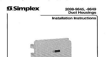
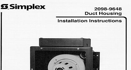
BSimDlex 9707 Housings 4 Instructions 1995 Simplex Time Recorder Co Gardner MA 01441.0001 1995 Simplex Equipment Co Ltd Mississauga Ontario L4V lH3 Canada specifications other were current as of publication are subject change without notice 038 574 698 9 95 DEVICE IS A DUCT SMOKE HOUSING WHEN PROVIDED WITH IT IS DESIGNED TO SAMPLE THE AIR FLOW PASSING BY IT IN AIR DUCT TO DETERMINE WHETHER CONTAINS LEVELS OF SMOKE EFFECTIVENESS OF A DUCT SMOKE SENSOR UPON HIGHLY THE DESIGN AND OPERATING CONDITIONS OF THE AIR HANDLING IN WHICH IT IS INSTALLED VARIABLES SUCH AS SMOKE DILUTION AND STRATIFICATION WHICH EVEN THE BEST DESIGNED SYSTEMS HAVE NO AND PROPER PLACEMENT AND POSITIONING OF THE DUCT SMOKE OFTEN COMPROMISED FOR PRACTICAL WHICH THE REASONS STATED ABOVE THE EFFECTIVENESS OF THIS SMOKE SENSOR CANNOT BE WARRANTED OR GUARANTEED NO CIRCUMSTANCES SHOULD THIS DUCT SMOKE SENSOR BE AS OR REGARDED TO BE A SUBSTITUTE FOR THE BUILDING FIRE ALARM AND DETECTION SYSTEM TO WHICH THIS IS ATTACHED AS A SECONDARY DETECTION DEVICE OF CONTENTS DESCRIPTION SETTING THE DUCT SENSOR ADDRESS Setting for the 2120 CDT System 4098 9707 only Setting for the 4020 4100 or 4120 System SPECIFICATIONS MAPNET II Operation with 24VDC Power for Relay Control II Power II Operation with 120VAC Power for Relay Control Supplementary Signaling Only 4 II Operation ROUTINES to Follow NOTES PROCEDURES Tube Selection Installation Tube Installation Tube Installation Procedures Installation and Duct Housing Testing Differential Pressure Test System Point Summaries with MAPNET II Addresses 2 MAPNET II Address Chart 3 MAPNET II Address Label 3 MAPNET II Operation with 24VDC Power for Relay Control 5 MAPNET II Operation with 12OVAC Power for Relay Control Supplementary Signaling Only 6 MAPNET II Operation 7 Duct Housing Placement Location of Bends or Inlets 9 Duct Housing Placement Location of Return Air Inlet 9 Duct Housing Placement Location of Dampers 9 Positioning 10 Tube Orientation 11 Tube Installation 11 Installation 13 Installation 14 Tear Out Sheet folowing an 8 digit Product ID number denotes ULC listed product WCommunication Net is protected by U S Patent No 4,796,025 DESCRIPTION 4098 9706 or 4098 9707 air duct sensor housing is designed to sample air and detect smoke in air ducts Only 4098 9706 has auxiliary contacts for alarm supervisory and control functions housing uses the 4098 9701 photoelectric sensor The housing must have a baffle installed Use the 4098 baffle with the 4098 9701 sensor is sampled via sampling tubes which extend into the duct The housing may be used with ducts from 8 inches to inches wide The housing may also be used on round ducts with diameters of 24 inches or greater housing has an Alarm LED Note A pulsing Alarm LED indicates On For detailed information on using smoke sensors in air distribution systems see NFPA 90A procedures that follow are used to install the 4098 9706 or 4098 9707 duct housing The instructions provided how to set the address at each housing and also how to make electrical connections The 4098 9706 and addressable smoke duct sensors are connected to a 2120 Multiplex Communications Device CDT 4098 9707 only or 4020 Fire Alarm Panel or 4100 Fire Alarm Panel or 4120 Fire Alarm by a single twisted shielded wire pair MAPNET II THE DUCT SENSOR ADDRESS sensor addressing is critical since the 2120 CDT 4020 4100 and 4120 Systems report alarms and troubles duct detector rather than per zone Each duct sensor has a unique address This address is associated with a