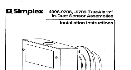
Simplex 4098-9750, -9751 TrueAlarm In-Duct Sensor Assemblies Installation Instructions

File Preview
Click below to download for free
Click below to download for free
File Data
| Name | simplex-4098-9750-9751-truealarm-in-duct-sensor-assemblies-installation-instructions-2614058397.pdf |
|---|---|
| Type | |
| Size | 1.96 MB |
| Downloads |
Text Preview
Q DEVICE WITH SENSOR BY UNACCEPTABLE A LOW VELOCITY IS DESIGNED TO SAMPLE THE AIR FLOW THE AIR DUCT TO DETERMINE WHETHER ASSEMBLY OF SMOKE EFFECTIVENESS UPON A DUCT SMOKE SENSOR HIGHLY THE DESIGN AND OPERATING SYSTEM WHICH IS INSTALLED THE AIR VARIABLES SUCH AS SMOKE DILUTION AND STRATIFICATION WHICH EVEN THE BEST DESIGNED SYSTEMS HAVE NO AND PROPER PLACEMENT AND POSITIONING OF THE DUCT SMOKE PRACTICAL OFTEN COMPROMISED WHICH THE REASONS STATED ABOVE THE EFFECTIVENESS OF THIS SMOKE SENSOR CANNOT BE WARRANTED OR GUARANTEED THIS DUCT SMOKE SENSOR NO CIRCUMSTANCES THE USED AS OR REGARDED REGULAR TO THIS DEVICE ATTACHED AS A SECONDARY DETECTION ALARM AND DETECTION BE A SUBSTITUTE OF CONTENTS DESCRIPTION THE IN DUCT SENSOR ADDRESS SETTING FOR THE 2120 CDT SYSTEM USE WITH 4098 9750 ONLY SETTING FOR THE 4010 4020 4100 OR 4120 SPECIFICATIONS SENSOR SENSOR ROUTINES INSTALLATION TO FOLLOW NOTES SENSOR INSTALLATION PROCEDURES EQUIPMENT AVAILABLE METHODS TEAR OUT SHEET following an a digit Product ID number denotes ULC listed product following an eight digit Product ID number denotes Global product The 2 suffix identifies market country with this suffix are not UL Listed is a Trademark of the Simplex Time Recorder Company Detection Detector Base is protected by U S Patent No 5,173,683 Communication Net is protected by U S Patent No 4,796,025 protected by U S Patent No 5,155,468 Simplex Time Recorder Company Gardner MA 01441 0001 U S A Simplex International Time Equipment Co Ltd Mississauga Ontario L4V 1 H3 Canada specifications and other information shown were current as of publication and are subject to change without notice Description 4098 9750 or 4098 975 1 TrueAlarm In Duct Sensor Assembly see Figure is designed to sample air and detect smoke in air ducts Only the 4098 9751 auxiliary contacts for alarm supervisory and control functions assembly uses the 4098 9714 Photoelectric Sensor supplied separately assembly is used with square ducts from 6 inches to 36 inches wide and 6 8 inch round duct s using the 6 inch or inch in duct adapter plate s adapter plate 4098 9819 8 inch adapter plate 409 9824 ordered For ducts 37 to 72 inches wide use an in duct sensor on both sides the duct to provide adequate sampling of the air volume housing has a red Alarm LED pulsing Alarm LED indicates On detailed information on using smoke sensors in air distribution systems see 90A procedures that follow are used to install the 4098 9750 or 4098 9751 In Duct Sensor Assembly The instructions provided show how to the address at each assembly and also how to make electrical connections smoke in duct sensors are connected to a 2120 Multiplex Device Transponder 4098 9750 only 4010 Fire Alarm Panel Fire Alarm panel 4100 Fire Alarm Panel or 4120 Fire Alarm Panel by a twisted shielded wire pair MAPNET 1 TrueAlarm Sensor Assembly the In Duct Sensor Address sensor addressing is critical since the 2120 Communicating Device CDT 4010,4020,4100 and 4120 Systems report alarms and per in duct sensor rather than per zone Each in duct sensor has a address This address is associated with a custom label which identifies physical location within a building The in duct sensor address and must match up with the address listed in the specification sheets of the 120 Job Configuration Report or Programmer Report for the 40 10,4020 or 4120 System You should have the appropriate specification sheets you during this part of the installation Setting System only the 2120 with 4098 Using the 2 120 Job Configuration Report find the entry for the in duct you are about to install The ZONE NAME column provides the while the DEVICE ADDRESS column provides the switch setting Using the switch setting data for the in duct sensor you are installing set in duct sensor address Locate the DIP switches on the in duct base Use a small screwdriver or pen to set the switches the switch setting data in the DEVICE ADDRESS column is ON while is switch OFF Recheck the location of the sensor and its address before electrical Setting 4120 the 4010 Using the Programmer Report for the 4010,4020,4100 or 4120 find entry for the in duct sensor you are about to install ZONE NAME a prefix and CUSTOM LABEL are located in the SYSTEM SUMMARY the 4010,4100 or 4120 System is shade


