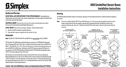
Simplex 4098-9784, -9785, -9786, & -9787 TrueAlarm Smoke Heat Sensor Bases Installation Instructions

File Preview
Click below to download for free
Click below to download for free
File Data
| Name | simplex-4098-9784-9785-9786-9787-truealarm-smoke-heat-sensor-bases-installation-instructions-7936018524.pdf |
|---|---|
| Type | |
| Size | 731.24 KB |
| Downloads |
Text Preview
Rev B are subject to change without notice specifications and other information shown were current as of publication 1997 Simplex International Time Equipment Co Ltd Mississauga Ontario L4V 1H3 Canada 1997 Simplex Time Recorder Co Gardner MA 01441 0001 U S A Detector Base is protected by U S Patent No 5,173,683 Analog Detection is protected by U S Patent No 5,155,468 II Communication Net is protected by U S Patent No 4,796,025 following an 8 digit Product ID number denotes ULC listed product 1 and 2 for compatibility between panel base and sensor 24VDC power for sounder or relay operation and are not to be used with the 2120 CDT See sensors receive both power and data over MAPNET II wiring The 4098 9786 and 9787 bases 4098 9787 bases are not to be used with 2120 CDT The 4098 9784 and 4098 9785 bases and CDT 4020 4100 or 4120 Panel by a single wire pair MAPNET II The 4098 9786 smoke heat sensor bases are connected to a 2120 Multiplex Communicating Device planned per local and national fire codes see NFPA 72 Chapter 5 sure that the location of each smoke sensor and each heat sensor has 1 2 OR PANEL PID MODEL NO CDT MAPNET II 4020 MAPNET II 4020 MAPNET II 4100 MAPNET II 4120 MAPNET II QTY OF PER 4020 4100 4120 CDT Panel compatibility identification marker is the model number of the panel Sensor compatibility identification marker is the model number found on the sensor label For detailed interconnection data see wiring diagrams in Document M 2120 CDT 4020 Field Wiring 841 842 4100 includes 4120 Field Wiring Diagram 841 731 and MAPNET II Devices Diagram 841 804 The 4098 9786 base is also suitable for use as a notification appliance in accordance with the of UL Standard 464 Heat Heat Ion Photoelectric following TrueAlarm sensors mount in the above bases sensor base has a unique address This address is associated with a custom label which identifies physical location within a building The base address and location must match up with the address in the specification sheets of the 2120 Job Configuration Report or the Programmer Report for 4020 4100 or 4120 System TrueAlarm smoke heat sensor bases Setting for the 2120 CDT System A SETTING THE BASE ADDRESS to Publication PER 21 015 574 663 when installing the 4098 9781 4098 9782 and Part D Accessory Installation page 5 for installing the 4098 9822 Relay Module with above bases with relay with sounder with remote LED the following procedures to install the following TrueAlarm smoke heat sensor bases Installation Instructions Smoke Heat Sensor 9785 9786 9787 F HEAT SENSOR INFORMATION the 4098 9731 or 4098 9732 heat sensors for property protection only Temperature Rate of Rise Sensor Functions temperature functions are software programmed and selectable from the following UL rating Temperature UL Maximum Ambient UL Maximum Coverage FM Maximum Coverage 57 68 Temperature 38 38 Ft Ft per minute per minute 4098 9731 and 4098 9732 heat sensors also provide general temperature monitoring within their range of 32 158 0 70 The 4098 9731 and 4098 9732 heat sensors do not protect life against fire smoke In most fires hazardous levels of smoke heat and toxic gases build up before a heat sensor initiates an alarm Independent studies that heat sensors should only be used where property protection is involved In cases where life safety is a factor the use of smoke is recommended Under no circumstances should the heat be relied on as the sole measure for ensuring fire safety Using the 2120 Job Configuration Report find the entry for the sensor base 4098 9784 and 4098 only you are about to install The CUSTOM LABEL column provides the location while the ADDRESS column provides the switch setting data Using the switch setting data for the base you installing set the base address Use a small or pen to set the switches the switch setting data in the DEVICE ADDRESS column is switch while is switch Double check the location of the sensor base and its address before proceeding to electrical Setting for the 4020 4100 or 4120 System Using the Programmer Report for the 4020 4100 or 4120 find the entry for the sensor base you about to install The device ADDRESS and CUSTOM LABEL are located in the SYSTEM SUMMARY under example Address M1 7 for the 4100 or 4120 system is circled in Figure 1 M1 is the channel while 7 is the device address on the channel For a base with Address M1 7 7 must be set on the base DIP switches SW1 Address 7 is circled in Table 3 For Address 4 7 circled in Figure 1 the identifies the MAPNET card address System POINT SUMMARY node 1 rev 1 WED 14 JUN 95 Point Summary ascending by zone name POINT SUMMARY Page 4 Label IO CARD 1 POINT IO1 IO CARD 1 POINT IO2 IO CARD 1 POINT IO3 IO CARD 1 POINT IO4 LAB BLDG 21 FLOOR EAST WING ROOM 18 FLOOR WEST WING ROOM 12 EAST WING ROOM 3 IO9 SFPUMP POINT SUMMARY 2 node 1 rev 1 WED 14 JUN 95 Point Summary ascending by zone name POINT SUMMARY Label