Simplex 4098-9793 IDNet Isolator Base for 4100ES, 4010ES, 4008, 4010, or 4100U IDNet (B) (C)

File Preview
Click below to download for free
Click below to download for free
File Data
| Name | simplex-4098-9793-idnet-isolator-base-for-4100es-4010es-4008-4010-or-4100u-idnet-b-c-1294603857.pdf |
|---|---|
| Type | |
| Size | 699.82 KB |
| Downloads |
Text Preview
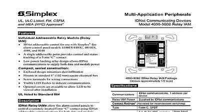
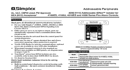
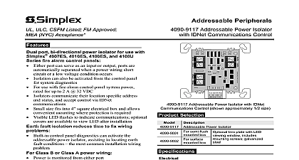
ULC CSFM Listed FM Approved NYC Acceptance Analog Sensing TrueAlarm Analog Sensors 4098 9793 IDNet Isolator Base base for TrueAlarm analog sensors IDNet addressable communications Compatible with Simplex fire alarm control panel 4100ES 4010ES 4008 4010 and 4100U When panel mounted quad isolation is also required for and 4010ES panels use IDNet Modules see notes and individual panel data sheets Can be installed up to 250 total allowing isolation to the device level 200 total with 4008 Base mounted LED indicates sensor status Designed for EMI compatibility UL listed to Standard 268 ULC listed to Standard S529 circuit wiring isolation is automatically separated from output when an communications short circuit occurs fault isolation reduces time to fix wiring Built in control panel diagnostics assist in locating earth conditions the most common installation wiring base 4098 9793 is compatible with Photoelectric sensor model 4098 9714 Heat sensor model 4098 9733 Multi sensor model 4098 9754 Class B or Class A wiring Communications are received from either input or output bases with Class A wiring to isolate short while still operating their sensors Sensing and IDNet communication The 4098 9793 IDNet Communications Base provides Simplex TrueAlarm analog sensor and also provides IDNet communications to improve installation convenience and increase integrity Isolation is automatically activated at the when an output short circuit is detected and isolation also be selected per base manually from the control to assist with troubleshooting wiring problems Isolator bases power up in isolation mode are directed to connect by the control panel If the wiring is acceptable the isolator base will connect the rest of the circuit If the output wiring is shorted isolator remains isolated This product is listed by the California State Fire Marshal CSFM pursuant to Section of the California Health and Safety Code See CSFM Listing 7300 0026 0217 allowable values and or conditions concerning material presented in this document for use City of New York Department of Buildings MEA35 93E Additional may be applicable contact your local Simplex product supplier for the latest Listings and approvals under Simplex Time Recorder Co are the property of Fire Protection Products 24V IDNET PW R PW R TIME RECORDER CO ONITOR ZAM CLASS B INSTR 574 183 CODE addressable device sensor Isolator Base TrueAlarm Sensor DOWN station sensor Channel with a Single 4098 9793 Isolator Base Fire Alarm Control Panel shown for reference Continued Tracking The isolator reports back to the panel it is in isolator mode and the extent of shorted is reported back to the panel by identifying device that are not communicating Isolators are sequentially to low number addresses to expedite Line Circuit SLC power up Refer to Instructions 574 709 and 574 707 for information Faults During installation earth faults often and finding these faults normally requires extensive disconnection With the 4098 9793 isolator base suspected to have earth faults can be isolated to in their discovery and repair 4 2013 Multi Floor Isolator Example 1 one line diagram on this page shows a multiple floor with Class B IDNet communications for each starting at an isolator base If any floor wiring the isolator base should experience a short circuit floor can be individually separated from the next the short circuit from disabling the entire communications wiring the event of an earth connection each floor can be isolated using the built in control panel With individual floor control the earth fault be isolated to the floor level to narrow the search area floor floor floor floor communications 2 wire wiring notes B riser IDNet IDNet Isolator with TrueAlarm sensor Notes Only IDNet communications wiring is shown Maximum resistance from panel to isolator and between isolators is 10 ohms Some IDNet devices require additional wiring for power Refer to specific devices for details NOTE For 4100ES 4010ES and 4100U systems if panel mounted IDNet Isolators are needed with remote isolators use an IDNet module with isolated output The 4100 3103 panel mounted Quad Isolator is compatible with MAPNET II Remote Isolators only Refer to data sheet S4100 0046 for the 4100 3107 Quad IDNet Isolator module and specific control panel data sheets for details Simplex Fire Alarm Panel model 4010ES for reference 4 2013 Multi Floor Isolator Example 2 illustration below is a modification of Example 1 for each floor has an additional isolator base and IDNet circuit is wired as a Class A connection With addition of these isolator bases wiring between floors be better protected in the event of a short circuit in the event of an earth connection the additional base per floor allows earth fault isolation to be with better precision isolator base examples on pages 2 and 3 show that as isolator bases are added to an IDNet addressable loop short circuit isolation and earth location can be obtained with a resolution level as to the single device as required floor floor floor floor Wiring Example A riser with Isolator using Class B taps device device communications 2 wire wiring notes A IDNet Circuit IDNet IDNet Isolator with TrueAlarm sensor Notes Only IDNet communications wiring is shown Maximum resistance from panel to isolator and between isolators is 10 ohms Some IDNet devices require additional wiring for power Refer to specific devices for details NOTE For 4100ES 4010ES and 4100U systems if panel mounted IDNet Isolators are needed with remote isolators use an IDNet module with isolated output The 4100 3103 panel mounted Quad Isolator is compatible with MAPNET II Remote Isolators only Refer to data sheet S4100 0046 for the 4100 3107 Quad IDNet Isolator module and specific control panel data sheets for details For Class A IDNet communications it is recommended that Remote Isolators or Isolator Bases be located close to the panel as the first and the last device as indicated not necessary when using the 4100 3107 IDNet module or other panel mounted IDNet module Simplex Fire Alarm Panel model 4100ES for reference 4 2013 Specifications for additional information refer to Installation Instructions 574 709 and 574 707 and Communications Specification Connections Listed Temperature Range Temperature Range Range Color Compatibility are ordered separately Isolator Products Mounting Information one address per base line resistance between panel and isolator or between isolators is 10 ohms AWG 0.82 mm2 780 ft 238 m terminals for in out wiring 18 to 14 AWG 0.82 to 2.08 mm2 F to 100 F 0 C to 38 C F to 122 F 90 C to 50 C to 95 RH from 32 F to 122 F 0 C to 50 C white Photoelectric Sensor Heat Sensor TrueSense Multi Sensor Remote IDNet Isolator Module 24 V Addressable Power Isolator not available 4008 control panels Sheet Reference Box Requirements octagonal or 4 square 1 1 2 deep gang 2 deep by others mount reference 102 mm box 102 mm box 38 mm box depth mount reference mount even with final or with up to 1 4 6.4 mm maximum recess mm Adapter Plate required for mounting surface mounted boxes and to 4 square flush mount boxes 162 mm