Simplex 4098 Heat Detectors Installation

File Preview
Click below to download for free
Click below to download for free
File Data
| Name | simplex-4098-heat-detectors-installation-7280345619.pdf |
|---|---|
| Type | |
| Size | 883.69 KB |
| Downloads |
Text Preview
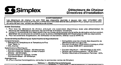
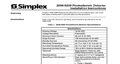
Cautions and Warnings Heat Detector Instructions NOT INSTALL ANY SIMPLEX PRODUCT THAT APPEARS Upon unpacking your Simplex product inspect the contents of carton for shipping damage If damage is apparent immediately file a claim the carrier and notify Simplex HAZARD Disconnect electrical power when making any adjustments or repairs Servicing should be performed by qualified Representatives HAZARD Static electricity can damage components Therefore as follows Ground yourself before opening or installing components use the 553 484 Control Kit Keep uninstalled components wrapped in anti static material at all times detectors are NOT life safety devices USE DETECTORS FOR PROPERTY PROTECTION For life safety requirements use smoke notes below pertain to all of the 4098 Heat Detectors covered in this Provide electronic supervision for all heat detectors with battery back up the Fire Alarm Control Panel FACP Where the possibility of positive airflow from the electrical conduit junction exists seal the conduit openings with 3M Weatherban 606 equivalent a non flammable sealing compound Refer to NFPA 72 for application test and maintenance requirements Use 14 18 AWG wire for connections to the heat detector Page Electrical Specifications and Approvals and Features publication covers the installation of 4098 Heat Detectors For a list of the covered and their general features see Table 1 This Publication following topics are covered in this publication and Weatherban are both trademarks of 3M 1999 Simplex Time Recorder Co Gardner MA 01441 0001 USA 1999 Simplex International Time Equipment Co Ltd Mississauga Ontario L4V 1H3 Canada specifications and other information shown were current as of publication and are subject to change without notice A Electrical Specifications and Approvals Electrical and Approvals following information contains general features specifications and for the 4098 Heat Detectors covered in this publication Rate of Rise and Fixed Temperature See Table 1 Alarm LED Compatible with 2 Wire Initiating Device Circuits Current Limited Alarm State when used with 2098 9211 Base only Specifications Standby Current 80 Microamps Alarm Current for Direct Connect Units 48 Milliamps Alarm Current for Base Connect Units 24 Milliamps Current 100 Milliamps at 32 VDC Range 15 32 VDC Ripple Voltage Allowed 30 UL consult Simplex Sales for additional listings and Features and Feature Table or Class 1 Models and Features 57 FT 57 FT RR 94 FT 94 FT RR 57 FT 57 FT RR 94 FT 94 FT RR 56.7 FT 56.7 FT RR 56.7 FT 56.7 FT RR 87.8 FT 87.8 FT RR 87.8 FT 87.8 FT RR 1 1 1 1 3 3 3 3 3 3 3 3 3 3 3 3 3 3 3 3 3 3 3 2 2 2 2 4 4 4 4 4 4 4 4 4 4 4 4 4 4 4 4 4 4 4 abbreviates Rate of Rise FT abbreviates Fixed Temperature denotes wiring directly connected to the heat detector with exception to the 2098 9211 base listed models are the 4098 9401 9402 9403 9404 9407 9408 9409 and 9410 Do not use models 4098 9407 9408 and 9410 with a 2098 9211 Current Limited Base on alarm verification circuits that employ a retard time greater than seconds following an 8 digit Product ID number denotes ULC listed product and Compatible to Table 2 and NFPA 72 for application test and maintenance Refer to Table 3 for maximum quantity of heat detectors allowed 2 wire initiating device circuit connected to compatible FACPs 2 Applications ID 9407 Temp Only 57 9408 and Rise 57 Spacing allowed x 60 ft x 18 m x 15 ft x 4.5 m x 70 ft x 21 m x 30 ft x 9 m violent temp and ceiling not exceeding 38 temp and ceiling not exceeding 38 violent temp and ceiling exceeding 38 but not 68 temp and ceiling exceeding 38 but not 68 9409 Only 94 x 60 ft x 18 m x 15 ft x 4.5 m 9410 and Rise 94 x 70 ft x 21 m x 30 ft x 9 m to NFPA 72 for application requirements other models listed in Table 1 consult Simplex Sales for application requirements 3 Compatibility for 2 Wire Initiating Device Circuits Initiating Device Circuit From Listed FACP Quantity of Heat Detectors Per Device Circuit ET FADM FABT VPBT ZAM LC HC IDNet ZAMs to Figures 1 and 2 for mounting and wiring direct connect detectors Connect wiring to terminals as shown Do not loop under terminals Break wire runs to provide of connectors SUPPLIED SEE NOTE 1 BOX SUPPLIED PLATE Use a 3 1 2 inch 8.89 cm or 10.16 cm octagonal box See Table 1 for detector model DETECTOR NOTE 2 1 Mounting of Direct Connect Detectors Use screws and wire clamps supplied with heat The recommended screw torque is inch pounds 17.29 kg cm See Table 1 for detector model See Table 3 for maximum of heat detectors per device circuit Use 14 18 AWG wire to to the heat detector BLADE SURFACE DETECTOR WIRES FOR EACH OF WIRE NOTES 2 NEXT DETECTOR E O L ALARM PANEL 4001 4002 4005 IDNet ZAMs 4100 OR 4120 2 Wiring of Direct Connect Detectors on next page Continued Continued to Figures 3 and 4 for mounting and wiring base connect detectors