Simplex 4098 Series TrueAlarm Sensors and Bases (Sensors 4098-9714 and 4098-9733) (B) (C)

File Preview
Click below to download for free
Click below to download for free
File Data
| Name | simplex-4098-series-truealarm-sensors-and-bases-sensors-4098-9714-and-4098-9733-b-c-5214037869.pdf |
|---|---|
| Type | |
| Size | 635.96 KB |
| Downloads |
Text Preview
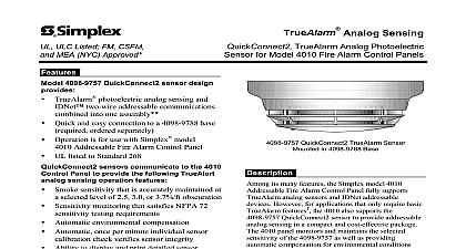
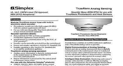
ULC CSFM Listed FM Approved NYC Acceptance Analog Sensing TrueAlarm Analog Sensors Photoelectric Heat Standard Bases and Accessories analog sensing provides Digital transmission of analog sensor values via IDNet MAPNET II two wire communications use with the following Simplex products 4100ES 4100U 4010ES and 4010 Series control and 4008 Series control panels with reduced set refer to data sheet S4008 0001 for details 4020 4100 and 4120 Series control panels Universal and 2120 TrueAlarm CDTs equipped MAPNET II operation alarm control panel provides Peak value logging allowing accurate analysis of each for individual sensitivity selection Sensitivity monitoring satisfying NFPA 72 sensitivity requirements automatic individual sensor check verifies sensor integrity Automatic environmental compensation multi stage operation and display of sensitivity directly in per foot Ability to display and print detailed sensor in plain English language smoke sensors provide Seven levels of sensitivity from 0.2 to 3.7 to additional information on page 3 sensors provide Fixed temperature sensing Rate of rise temperature sensing Utility temperature sensing Listed to UL 521 and ULC S530 features Listed to UL 268 and ULC S529 Louvered smoke sensor design enhances smoke by directing flow to chamber entrance areas minimally visible when ceiling mounted Designed for EMI compatibility Magnetic test feature is provided Optional accessories include remote LED alarm and output relays base reference For isolator bases refer to data sheet S4098 0025 For sounder bases refer to data sheet S4098 0028 For photo heat sensors refer to data sheet S4098 0024 address and S4098 0033 dual address These products have been approved by the California State Fire Marshal CSFM pursuant to 13144.1 of the California Health and Safety Code See CSFM Listings 7271 0026 231 7270 0026 216 and 7300 0026 217 for allowable values conditions concerning material presented in this document Accepted for use City of York Department of Buildings MEA35 93E Additional listings may be applicable your local Simplex product supplier for the latest status Listings and approvals under Time Recorder Co are the property of Tyco Fire Protection Products TrueAlarm Photoelectric Mounted in Base Communication of Analog Sensing analog sensors provide an analog digitally communicated to the host control using Simplex addressable communications At the panel the data is analyzed and an average value is and stored An alarm or other abnormal is determined by comparing the sensor present against its average value and time Data Evaluation Monitoring each sensor value provides a continuously shifting reference This software filtering process compensates for factors dust dirt etc and component providing an accurate reference for evaluating new With this filtering there is a significant reduction the probability of false or nuisance alarms caused by in sensitivity either up or down Panel Selection Peak activity per sensor is to assist in evaluating specific locations The alarm point for each TrueAlarm sensor is determined at the control panel selectable as more or less sensitive as individual application requires Selection Sensor alarm set points be programmed for timed automatic sensitivity such as more sensitive at night less sensitive day Control panel programming can also provide operation per sensor For example a 0.2 may cause a warning to prompt investigation while a level may initiate an alarm Alarm and Trouble LED Indication Each base LED pulses to indicate communications the panel If the control panel determines a sensor is alarm or is dirty or has some other type of trouble the are annunciated at the control panel and that sensor LED will be turned on steadily During a system the control panel will control the LEDs such that LED indicating a trouble will return to pulsing to help the alarmed sensors 4 2013 Description sensor bases contain integral addressable that constantly monitor the status of the photoelectric or heat sensors Each sensor is digitized and transmitted to the system fire alarm panel every four seconds TrueAlarm sensors use the same base different types can be easily interchanged to meet specific requirements This feature also allows intentional substitution during building construction When are temporarily dusty instead of covering the sensors causing them to be disabled heat sensors be installed without reprogramming the control Although the control panel will indicate an sensor type the heat sensor will operate at a sensitivity providing heat detection for building at that location Reference Box Requirements boxes are by others relay 4 octagonal or 4 square 1 1 2 deep gang 2 deep relay 4 octagonal or 4 square 1 1 2 deep 1 1 2 extension ring 102 mm Square Box 102 mm Octagonal Box mount reference 38 mm box depth mount reference mount even with final or with up to 1 4 6.4 mm maximum recess Relay mounts in electrical box or remotely Relay mounts base electrical box Sensor Bases and Accessories Base Features mounted address selection Address remains with its programmed location Accessible from front DIP switch under sensor features Automatic identification provides default sensitivity substituting sensor types red LED for power on pulsing or alarm or steady on Locking anti tamper design mounts on standard outlet Magnetically operated functional test Bases Standard sensor base Sensor base with wired connections for 2098 9808 Remote LED alarm indicator or 4098 9822 unsupervised Sensor base with supervised relay driver not compatible with 2120 CDT Relay operation is programmable and can be manually from control panel Use with remote mount 2098 9737 relay Also includes wired connections for remote LED alarm or 4098 9822 relay Base Options Remote or local mount supervised relay DPDT contacts for resistive suppressed loads power rating of 3 A 28 VDC non power limited of 3 A 120 VAC requires external 24 VDC power LED Annunciation Relay Activates when base LED is on steady indicating local or trouble DPDT contacts for resistive suppressed loads power rating of 2 A 28 VDC non power limited of 1 2 A 120 VAC requires external 24 VDC power Adapter plate Required for surface or semi flush mounting to square electrical box and for surface mounting to octagonal box Can be used for cosmetic retrofitting to existing 6 3 8 base product Remote red LED Alarm Mounts on single gang box in illustration to right Size 2 1 2 X 1 1 2 X 1 3.75 cubic inches mm X 38 mm X 25.4 mm Review total wire count wire size and accessories wired to determine required box volume 162 mm mm Adapter Plate required for to surface mounted boxes and 4 square flush box 124 mm mm Bases 9791 9792 4 2013 Sensors against rear air flow entry mounting shielded electronics sensors Selectable rate compensated fixed temperature with or without rate of rise operation Rated spacing distance between sensors Temp F C F C ULC ft x 60 ft m ft x 40 ft m Spacing Either Fixed Setting ft x 20 ft 6.1 m fo